Unloading & assembly – MacDon 974 FlexDraper User Manual
Page 83
Form # 147083
Issue 01/07
81
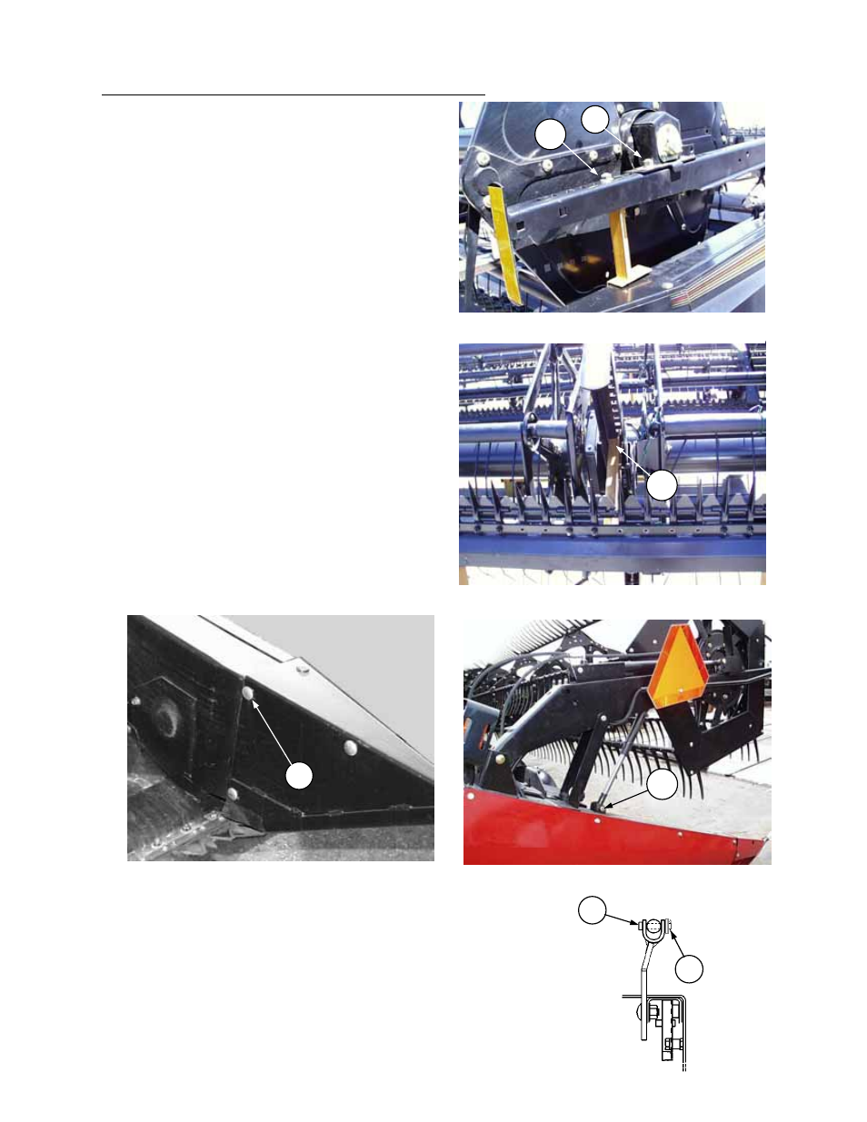
REEL LIFT CYLINDERS WORKING POSITION
B
UNLOADING & ASSEMBLY
REEL SUPPORT ARMS – 30’, 36’ & 39’ Split Reel Headers
1. Drive forklift to front of header, centered on the R/H
reel. Remember L/H and R/H designations are
determined from the rear of the header, facing
forward. Place a lifting strap around reel main tube and
attach to forklift.
NOTE: To avoid damage to tube, do not lift with
forks directly under reel tube.
2. Remove nuts (A) securing yellow shipping supports
to L/H & R/H reel support arms.
3. At center of header, remove nut securing yellow
shipping support (C) to center reel support arm.
4. Raise the forks slowly to raise R/H reel. Engage reel
props at R/H end and center support arms and
lower forks until reel rests on props.
5. Disengage center reel arm shipping support from
cutterbar and discard.
6. Drive the forklift to L/H end of left reel. Place lifting
strap around reel main tube and attach to forklift.
Raise the forks slowly to raise L/H reel. Engage reel
prop at L/H end and lower forks until reel rests on
prop. Back the forklift away.
7. Remove the bolts securing left and right end
shipping supports to header frame. Discard straps
and re-install hardware. Hardware at (F) is installed
reversed for ease of access when removing
shipping supports. To prevent damage to reel end
shields and /or discs, always install carriage head
bolts to the inside of header as shown for field use.
8. Cut shipping wire securing reel lift cylinders. At outer
arms, attach rod end of reel lift cylinder to header
at (B). At center arm, attach rod end of cylinder to
reel support arm. Bleed air from cylinders per
instructions on page 85.
974 Reel Fore-Aft Cylinders:
1. Cut shipping wire securing reel fore-aft cylinders. Prior to attaching fore-
aft cylinders, bleed air per instruction on page 85.
2. After bleeding, attach cylinders to fore-aft supports at end of reel arms. At
center arm, install clevis pin with head at (D) as shown, and use 21/32
ID washer(s) as required to maximize clearance between pin head
and reel end shield. Secure clevis pin with cotter pin (E). Move reel
manually to line up pinholes
3. Remove bolt (G) (see photo top left) securing reel end supports to reel
arms.
CENTER REEL SUPPORT ARM
C
REEL SUPPORT ARMS SHIPPING POSITION
A
G
INSTALL HARDWARE WITH HEADS IN
F
E
D