Operation – MacDon 974 FlexDraper User Manual
Page 25
Form # 147083
Issue 01/07
23
OPERATION
HEADER FLOTATION ADJUSTMENT – 974 FLEX
HEADERS
Cutting on the Ground (Operating Tips continued)
3. Disengage wing float lock pins (Position (B), two
per side) to allow wings to float.
4. Adjust float optimizer while watching float indicator
to set desired cutterbar down force (flotation).
5. Adjust header angle to achieve desired stubble
height. NOTE: Use steps 4 and 5 to fine tune the
header to achieve the shortest stubble height
without pushing dirt
6. In rocky fields, adjust skid shoes down. This raises
guards when operating at the flattest header angle
to minimize scooping rocks.
7. If cutterbar begins to push dirt during operation,
adjust header height (with optimizer or feeder
house height control) to minimize pushing.
8. Header angle and reel fore-aft position can be
changed without significantly effecting header
flotation.
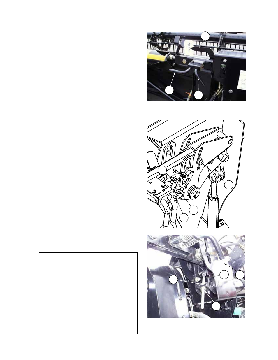
Adjust Wing Downforce To Correct Uneven Float:
1. If stubble at dividers is longer than at center, or if
cutterbar pushes dirt in the center section of the
header, adjust to transfer weight from the center
section to the wings as follows:
• Loosen bell crank clamp bolt (C), located inside bell
crank housing.
• Loosen nut (D) and turn nut (E) to raise bell crank
bolt (F).
• Tighten clamp bolt (C).
• NOTE: Make small adjustments in position of tee
bolt (one or two turns) followed by field test. If the tee
bolt is adjusted more than 10 turns in total, perform
the entire “Wing Float Set-Up” procedure detailed on
page 87.
2. If stubble at center of header is longer than at dividers,
or if cutterbar pushes dirt near the ends of the header,
proceed as in Step 1, but lower the tee bolt to transfer
weight from the wings to the center section.
3. When properly adjusted, the wing float indicators (G)
will be moving continuously, indicating header wings
are flexing between “smile” and “frown”. If not, re-
adjust as required per steps 1 & 2.
B
A
WING FLOAT LOCKOUT:
(A) – ENGAGED / (B) – DISENGAGED
G
ADJUST BELL CRANK BOLT –
UP FOR HEAVIER WING / DOWN FOR
LIGHTER WING
C
D
F
E
NOTE: Functions of inner and outer wing
float lock pins – Each wing of the Flex Header
has an inner and outer float lock-out pin as
shown in top photo above. These pins can be
engaged (as at (A) above) or disengaged (as at
(B) above) with the following results:
• Both pins engaged – Wing float is fully
locked out.
• Inner pin engaged, Outer pin disengaged –
Wing can smile, not frown.
• Outer pin engaged, Inner pin disengaged –
Wing can frown, not smile
• Both pins disengaged – Wing is free to flex
to smile and frown positions.
C
E
F
D