A-star 32u4 micro, A-star 32u4 micro pinout and components, Pinout – Pololu A-Star 32U4 User Manual
Page 5: Leds, Connectors
3. A-Star 32U4 Micro
3.1. A-Star 32U4 Micro pinout and components
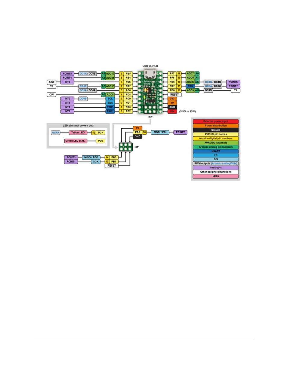
Pinout
The diagram above identifies the I/O and power pins on the A-Star 32U4 Micro; it is also available as a
(409k pdf). For more information about
the ATmega32U4 microcontroller on this board, see
Printed on the A* circuit board are indicators that you can use to quickly identify each pin’s capabilities: a triangle
next to the pin means it can be used as an analog input, and a square wave symbol under the pin number means it can
be used as a PWM output.
LEDs
The A-Star 32U4 Micro has two indicator LEDs.
The
yellow
LED is connected to Arduino pin 13, or PC7. You can drive this pin high in a user program to turn this
LED on. The
fades this LED on and off while it is waiting
for a sketch to be loaded.
The
green
LED is connected to PD5 and lights when the pin is driven low. While the board is running the A-Star
32U4 Bootloader or a program compiled in the Arduino environment, it will flash this LED when it is transmitting
data via the USB connection.
Connectors
The A-Star 32U4 includes a USB Micro-B connector that can be used to connect to a computer’s USB port via a
(not included). The USB connection can be used to transmit
Pololu A-Star 32U4 User’s Guide
© 2001–2014 Pololu Corporation
3. A-Star 32U4 Micro
Page 5 of 30