A-star 32u4 mini sv regulator, A-star 32u4 mini schematic and dimensions, Schematic diagram – Pololu A-Star 32U4 User Manual
Page 13
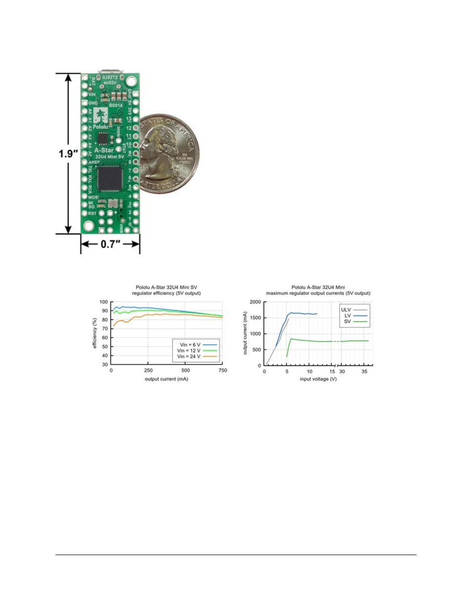
A-Star 32U4 Mini SV, bottom view with
dimensions.
4.4. A-Star 32U4 Mini SV regulator
The A-Star Mini SV can be powered from a 5 V to 36 V external
source. The input voltage is regulated to 5 V by a 500 mA ISL85415
switching step-down (buck) converter from Intersil. (We also make
a
based on
this integrated circuit.)
As shown in the left graph below, the SV’s switching regulator has
an efficiency – defined as (Power out)/(Power in) – of 80% to 95%
for most combinations of input voltage and load.
The A-Star’s components, including the microcontroller and LEDs, draw 30 mA to 40 mA in typical applications.
The rest of the regulator’s achievable output current, which depends on input voltage as well as ambient conditions,
can be used to power other devices. The right graph above shows output currents at which the voltage regulator’s
over-temperature protection typically kicks in after a few seconds. These currents represent the limit of the regulator’s
capability and cannot be sustained for long periods; a good estimate for the maximum continuous regulator output
current is 60% to 70% of the values shown in the graph or 500 mA, whichever is lower (the regulator is not rated for
operation above 500 mA).
4.5. A-Star 32U4 Mini schematic and dimensions
Schematic diagram
The schematic diagram for the A-Star 32U4 Minis is available as a PDF:
(451k pdf).
Pololu A-Star 32U4 User’s Guide
© 2001–2014 Pololu Corporation
4. A-Star 32U4 Mini
Page 13 of 30