Motors – Pololu Qik 2s12v10 User Manual
Page 7
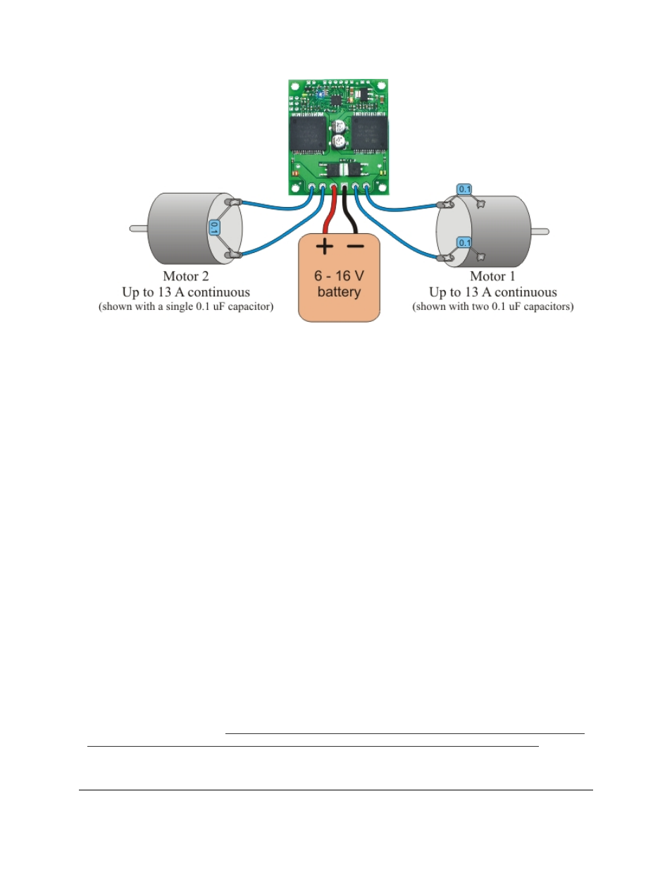
Qik 2s12v10 power and motor connections.
Motors
The qik can independently drive up to two bidirectional brushed DC motors, referred to as M0 and M1. The
two terminals of each motor should be connected to the qik as shown above. Variable speed is achieved with
7-bit or 8-bit pulse width modulated (PWM) outputs at one of several selectable frequencies. 7-bit control allows
for PWM frequencies of 19.7 kHz, 2.5 kHz, and 310 Hz; 8-bit control allows for PWM frequencies of 9.8 kHz,
1.2 kHz, and 150 Hz. The highest achievable frequency of 19.7 kHz is ultrasonic, which can result in quieter
motor control. Lower frequencies might make the motors louder, but they can help decrease power losses due to
switching and affect the relationship between PWM duty cycle and motor RPM. The resolution and frequency can
be set via the qik’s PWM configuration parameter (see
The motor direction convention used in this document is that “forward” corresponds to holding the + output at
VIN while PWMing the - output between ground and high impedance. “Reverse” is the same as forward but with
the outputs flipped: - is held at VIN while + is PWMed between ground and high impedance. As a result, the
motor is rapidly alternating between drive and coast when the direction is “forward” or “reverse”. Variable speed
control is achieved by varying the fraction of the cycle that the motor outputs are driving. Full speed arises when
the motor outputs are driving 100% of the time (one motor output is held at VIN and the other at ground). See
for more information.
The qik 2s12v10 allows for variable braking. In this mode, the motor’s + and - outputs are PWMed between
ground and high impedance. While the outputs are high-impedance, the motor coasts, and while the outputs are
tied to ground the motor brakes. See
for more information.
The qik 2s12v10 motor controller uses VNH2SP30 motor driver integrated circuits. These motor drivers have
maximum current ratings of 30 A continuous, but the chips by themselves will overheat at lower currents (see
the table below for typical values). The actual current the qik can deliver will depend on how well the motor
drivers are kept cool. The qik’s printed circuit board is designed to draw heat out of the motor driver chips, but
performance can be improved by adding a heat sink. In our single-driver tests, we were able to deliver 30 A for
a fraction of a second and 20 A for several seconds without overheating the IC. At 6 A, the chip gets just barely
noticeably warm to the touch. For high-current installations, the motor and power supply wires should also be
soldered directly instead of going through the supplied terminal blocks, which are rated for up to 15 A.
Qik 2s12v10 User's Guide
© 2001–2012 Pololu Corporation
3. Connecting the Qik
Page 7 of 33