Rs485 data line, Control unit installation, Rs485 data line resistance checks pc installation – Paxton Net2 classic quickstart guide User Manual
Page 2
2
Page
90% of installation faults are caused by wiring errors on the RS485 data line.
Special attention to getting this right first time saves a lot of time and effort.
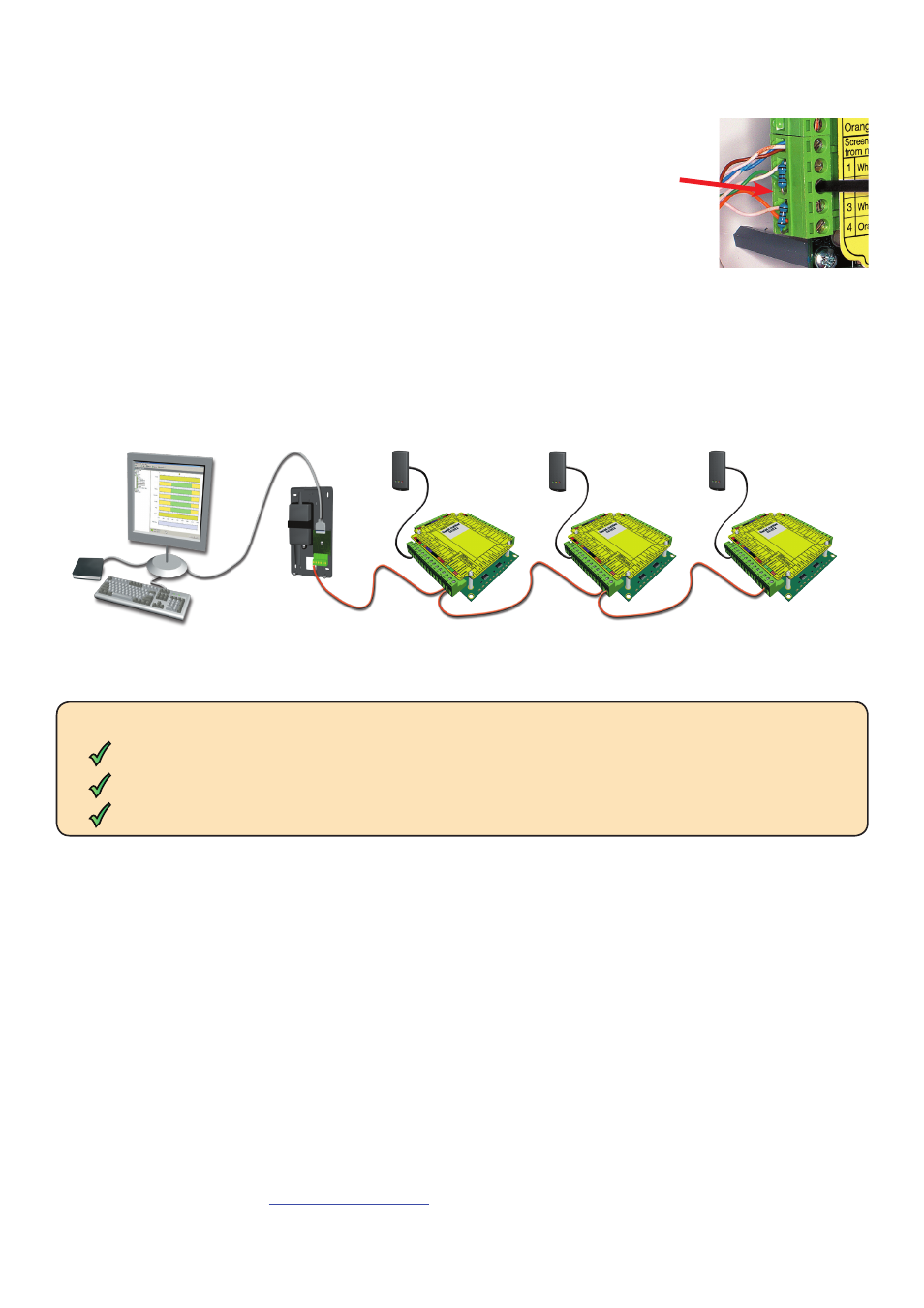
RS485 data line
The data line must be wired in a single daisy chain. The data converter may be located anywhere along the data
line. 120 ohm terminating resistors must be linked across each data pair at the beginning AND end of the line.
This can be done on many units with a switch or jumpers. If not, free resistors are provided with the converter.
The example below requires terminating at the RS485 converter and also the 3rd ACU at the end.
Control unit installation
Wire the components to the Access Control Unit (ACU) as shown on the first page. This will include:
- Reader/Keypad
- Electric Lock
- Power supply
- Any other optional components
Press the exit button or in the absence of an exit button, short the 0V and exit terminals together. The lock relay
LED will come on and the lock should release.
RS485 data line resistance checks
PC Installation
The current specification for compatible PC hardware, network and operating systems is available on our
website at the following link:
http://paxton.info/720
The reader's default indication has all the LED's on. Access granted is denoted with a single flashing Green LED.
Access Denied is a single flashing Red LED.
Check the screen of the data cable is continuous - this provides the 0V DC system reference.
Check that there are no data line to screen shorts.
Check the resistance across each data pair is 60-80 ohms.
Power down all TCP/IP, USB and RS232 converters (individual and Net2 plus).
End of Line Termination
120 ohm resistors must be linked across each data pair at the beginning AND end of
the data line. This can be done on many units with a switch or jumpers. If not, free
resistors are provided with the converter. If the data converter is located at a point along
the data line, termination will then be required in the two ACU's at each end of the line.
Reader & Data Cable Screens
- Data cable screens and spare cores MUST be connected throughout.
- Reader and keypad screens where provided, should be connected to the Black 0V terminal.