Wiring hands free interface, Connection modules – Paxton PROXIMITY P200 & P200E metal mount reader User Manual
Page 2
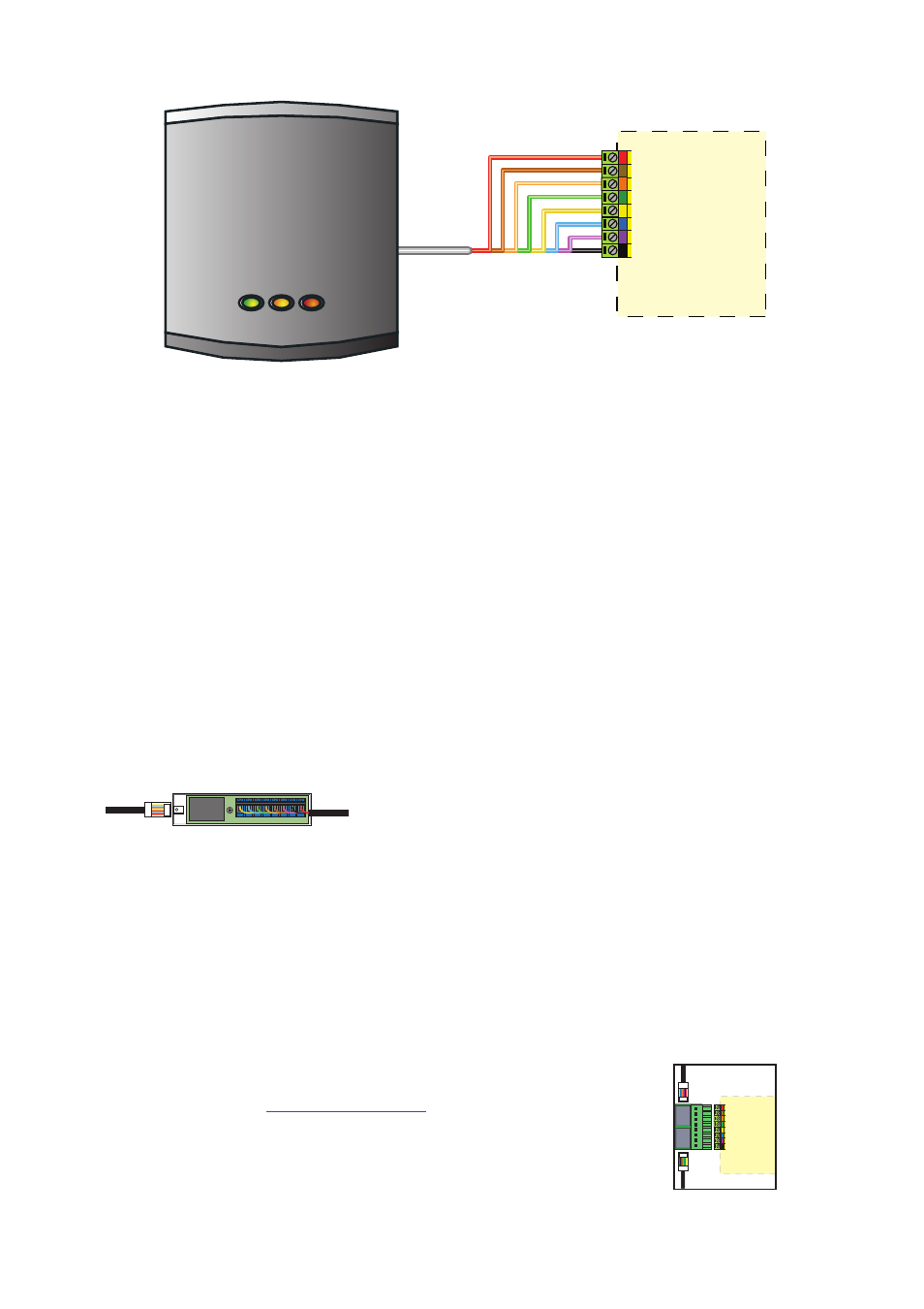
Wiring
Hands free interface
The interface should be positioned as close as practical to the reader. A distance from interface to reader of 10
to 15 meters can be achieved but wireless technology is susceptible to environmental factors and so if problems
are experienced it may be necessary to move the interface closer to the reader.
The hands free interface should not be housed in a metal enclosure as it contains the main receiver aerial.
Sticky feet allow the interface to be stuck to the ACU wiring label in a PSU plastic housing.
WHITE labelled control units provide 5V at the Red terminal. The Red power wire for the
reader should therefore be directly connected to the 12V supply terminal.
The reader port module is designed to convert the
standard reader ports on Switch2 and Net2 controllers
to accept one or two RJ45 connections. Pull off the
screw terminal block from the reader port and simply
replace it with this module.
This module can be used to provide a
connection point for the reader RJ45 plug.
The terminals on the module are then wired
colour for colour to the controller.
Alternatively, the reader can be wired directly
into the screw terminals of the control unit by
first cutting off the RJ45 plug and stripping
back the wires in the cable.
Reader port module (325-030)
This module may be purchased separately to speed up
the installation and replacement of readers.
Connection modules
Further information on how to purchase Installer Tools is available at:
http://paxton.info/841
Reader junction box (325-020)
Connection to a control
unit reader port