Paxton Demonstration Case - TCP/IP User Manual
Paxton
14/11/2011
Quickstart guide
The demonstration case contains the hardware required to show all the functions of an operating Net2 system.
Reader 1 is a KP unit that can be used to demonstrate proximity and keypad functions or a combination of both
(e.g. Card + PIN).
Plug the mains cable into the connection as shown on the diagram. Power on the unit by means of the switch and
the power LED should illuminate. The ACU should display 5V, 12V and a flashing OK LED.
Connect your PC to the LAN port via a crossover cable (supplied) and then set up the ethernet connection as per
the instructions on page 2.
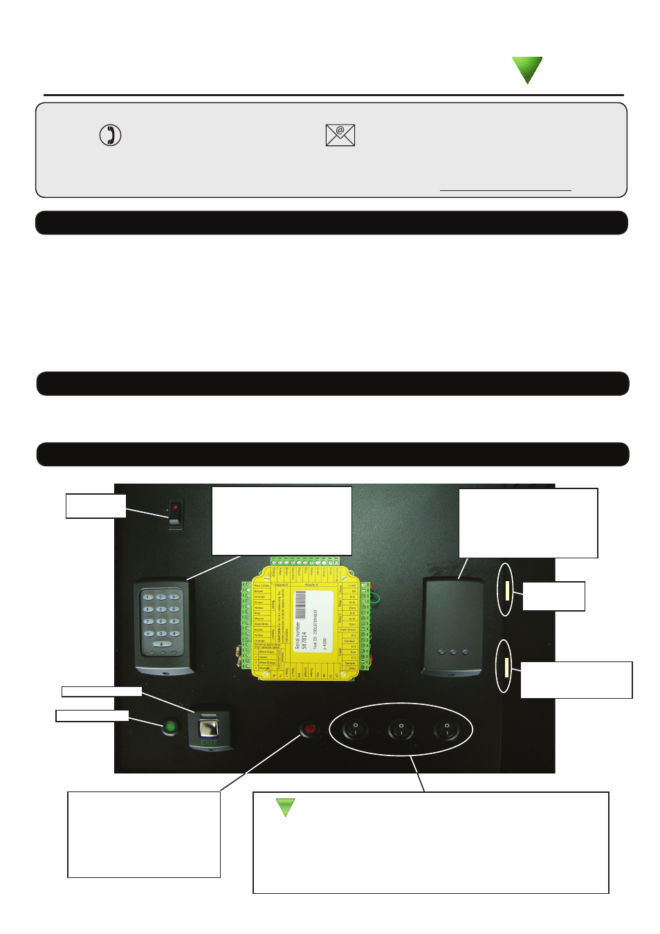
Layout
P series reader
Reader 2 is a standard
P50 reader
K P Reader
Reader 1 is a combined
keypad / proximity unit
Input Functions
• Contact: The door contact input (Closed when door in frame)
• Tamper: Simulates a signal from a tamper switch (Enclosure opened)
• PSU: Simulates a Mains Failure signal from a monitored power supply.
On/Off
Switch
Power LED
Q
Alarm LED
The LED displays the condition
of the General Alarm Output.
(An external alarm would be
ringing while the LED is On)
Exit button
TCP/IP LAN
(crossover cable
required)
A full range of application notes and tutorials are available to guide you through the set-up and operation of the
Net2 system. - Just click on the Documentation icon on the Net2 welcome screen for the complete list.
Documentation
AC Mains
Connection
Ins-30044 Demonstration Case - TCP/IP
Technical Support
Technical help is available: Monday - Friday from 07:00 - 19:00 (GMT)
Saturday from 09:00 - 13:00 (GMT)
01273 811011
Documentation on all Paxton products can be found on our website - http://www.paxton.co.uk/
Paxton