Specifications, Status lights features statement of conformity, Warnings – Paxton I/O board with 2A/12V DC boxed power supply User Manual
Page 3
-20 °C
+45 °C
13V DC
13.8V DC
2A
1A
100V AC
240V AC
+/- 10%
1.2A
50 Hz
60 Hz
+/- 3 Hz
4
4
240V AC
13 A
4 kV AC
* 400 mA
232 mm
320 mm
80 mm
236 mm
320 mm
80 mm
150 mm
100 mm
62 mm
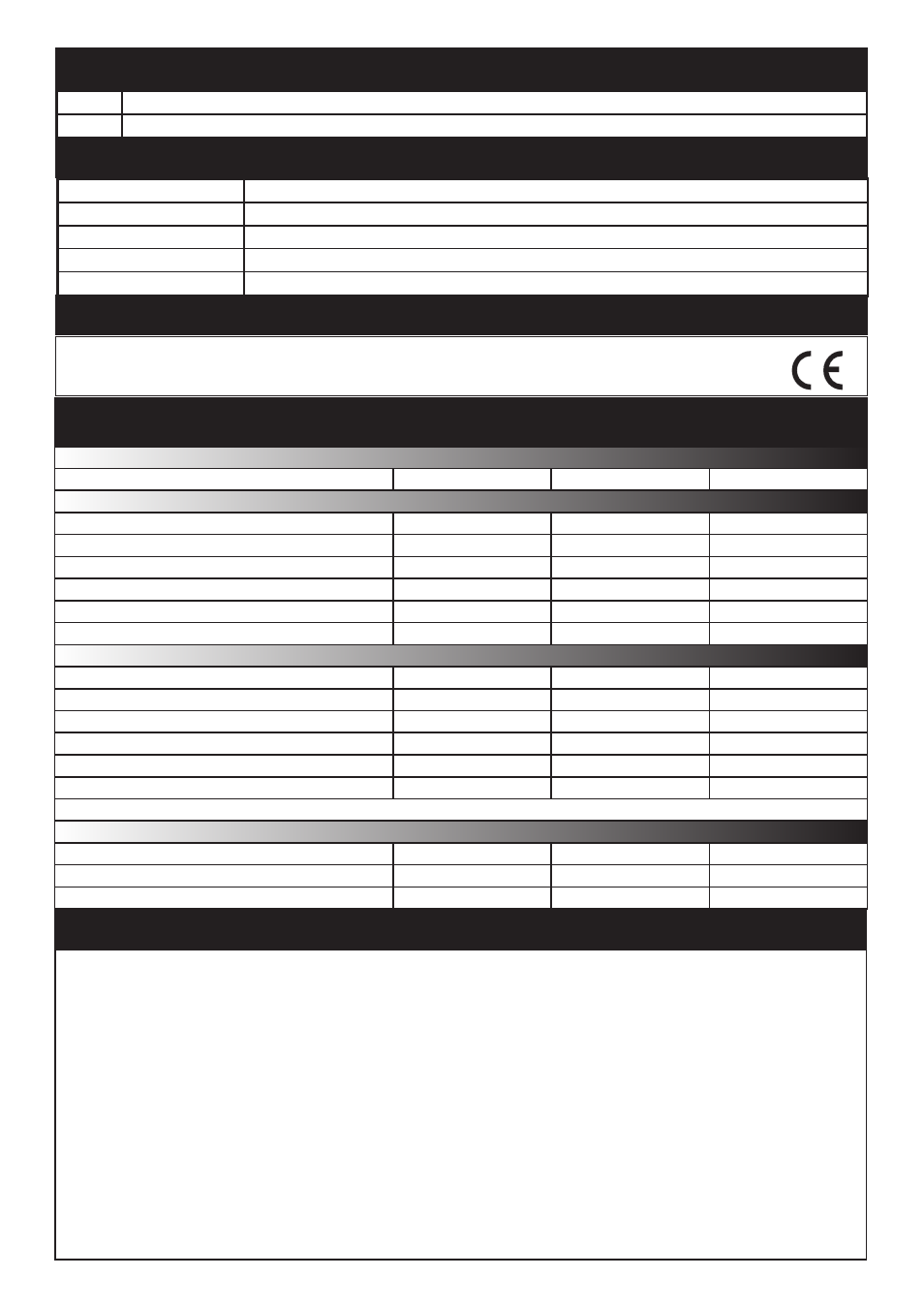
Specifications
Operating temperatures - all items
PSU Electrical
Output voltage
Maximum load output current
Maximum battery charging current
Mains supply voltage
Mains supply current
Mains supply frequency
Status Lights
Features
Statement of Conformity
The Low Voltage (LVD) Directive - 2006/95/EC
The Electro-Magnetic Compatibility (EMC) Directive - 2004/108/EC
The Restriction of Hazardous Substances (RoHS) Directive - 2002/95/EC
Green
Red
Battery backup
Fast/Trickle charge
Deep discharge protection
Mains failure alarm (PSU)
Tamper alarm
This LED is on when the input supply has failed - Power is being supplied by the battery.
This LED is on when the input supply is healthy.
The cabinet can accommodate a 12V / 7Ah battery.
The battery is continuously charged to keep it at maximum capacity.
If battery voltage falls below 9.5V, it will automatically disconnect - Red LED goes out.
Registers an alarm if the mains power fails when connected to an ACU or I/O board.
Registers an alarm if the lid is opened when connected to an ACU or I/O board.
Environment
Metal Cabinet
Plastic Cabinet
Battery Compartment (Plastic Housing)
Dimensions
:
The following warnings and instructions MUST be adhered to. Read the instructions before installing and powering
the equipment. Keep the instructions in a safe place for future reference.
:
RECEIVING INSPECTION- Remove any traces of packing material from the unit as such debris may create a fire or shock
hazard. Unpack the unit with care and inspect for transit damage. If damage is suspected, the unit must not be used or tested,
but should be returned to Paxton for investigation and the damage reported to the carrier.
:
INSTALLATION- Only qualified and trained personnel, familiar with this type of product and who fully understand these
instructions should install, connect or test this equipment. There are no user serviceable parts within the PSU unit.
:
- The equipment is intended for indoor use only in dry locations. This is a Class A product. In a domestic environment this
product may cause radio interference in which case the user may be required to take adequate measures.
:
- The installation must meet National Wiring Regulations and IEC60950-1 standards.
:
- Disconnect Devices: A readily accessible disconnect device shall be incorporated in the building wiring to include an
appropriately rated circuit breaker to disconnect both poles with at least a 3.0 mm contact gap. After switch off, all internal
capacitors will discharge to safe levels within 60 seconds under normal conditions. Under fault conditions, charge may be held for
much longer and suitable precautions should be taken before handling the unit.
:
- Protection device: The fusing characteristics of the protection device to be used are T3.15AH250V
WARNINGS
Max
Height
Width
Depth
Min
Min
Max
I/O Electrical
Min
Max
Relay contact isolation
Relay voltage rating
Relay current rating
Relay inputs
Relay output
Current
*This max value is for when all four relays are energised