Wiring, Positioning readers, Read in, read out – Paxton OEM PROXIMITY Long range reader - EM4100 - Wiegand Output User Manual
Page 2: Interface module reader module
2t
e
N
Co
nt
r
ti
n
Ul
o
G
r
D
EL
ne
e
E/ti
x
E
nt
ry
V0
V2
1
Net2A
ir I nt
erfa
ce
R
re
da
e
Not Connected
Not Connected
Not Connected
A seperate power supply must be
connected here for the reader to
function
Blue/Clock/D1
Yellow/Data/D0
Red/Interface On
Green/Green LED
Orange/Interface Comms
Brown/Red LED
12V
0V
Mauve/Not Used
Black/0V
Not Connected
Blue/Clock/D1
Yellow/Data/D0
Red/Interface On
Green/Green LED
Orange/Interface Comms
Brown/Red LED
12V
0V
Test Jumper and Connector
Test Purposes only - Not required during Installation
Mauve/Not Used
Black/0V
Not Connected
Blue/Clock/D1
Yellow/Data/D0
Red/Interface On
Green/Green LED
Orange/Interface Comms
Brown/Red LED
12V
0V
Mauve/Not Used
Black/0V
Not Connected
Blue/Clock/D1
Yellow/Data/D0
Red/Interface On
Green/Green LED
Orange/Interface Comms
Brown/Red LED
12V
0V
Test Jumper and Connector
Test Purposes only - Not required during Installation
Mauve/Not Used
Black/0V
Not Connected
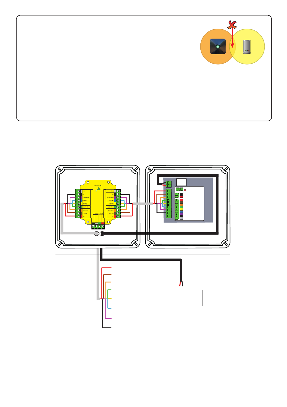
Wiring
Read in, read out
When using in and out readers, users may be picked up by both readers as they move through the door which
will reduce the reliability of any roll call or anti-passback application. Ensure that sufficient spacing is provided
between these readers for optimum range and reliability.
Positioning readers
For maximum read range the hands free reader field should not be overlapped
by the field from other interference sources at or around 125 kHz. These
include Loop readers, OEM readers, etc.
Readers should not be positioned so that their active fields overlap.
(see table on back page for typical hands free read ranges)
For optimum keyfob battery life please choose your reader location carefully to avoid placing it within hands
free range of work stations, rest or smoking areas.
You will see that the interface is mounted upside down in the housing.
This is to position the internal aerial away from other reader components and is intentional.
Interface Module
Reader Module
+12V DC
Red LED
Amber LED
Green LED
Data 1
Data 0
Not Required
0V
To 12V DC power
supply