Multiquip DCA100SSJU User Manual
Page 37
DCA-100SSJU — PARTS AND OPERATION MANUAL (STD)— REV. #2 (05/03/01) — PAGE 37
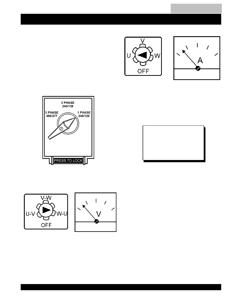
How to read the output terminal gauges.
The gauges and knobs on the control panel DO NOT effect
the generator output in any fashion. They are there to
simply help the operator observe how much power is being
supplied produced at the UVWO legs.
When the Voltage selector switch is in the 240/120V
position (see figure 17), place the AC Voltmeter Change-
over switch to the W-U position and the AC ammeter
Change -over Switch to the U or W position to read the
output on the selected leg.
FIGURE 17. Voltage Selector Switch 240/120V Single Phase
Position
FIGURE 18. AC Voltmeter
Change-over switch
(Reading the W-U leg on
the output terminal panel)
FIGURE 21. AC Ammeter
(Amp reading on U lug)
FIGURE 20. AC Ammeter
Change-over Switch
(Reading the U leg on the
output terminal panel)
FIGURE 19. AC Voltmeter
Guage
(Volt reading on W-U Lug)
When using plural single phase
voltages, make sure to balance
the load on each of the single
phase legs.
NOTE
DCA-100SSJU — OUTPUT TERMINAL PANEL OVERVIEW
Table of Contents