Maintenance, Trowel arm adjustment, Spider removal – Multiquip HHNG5 User Manual
Page 33
HHNg5 RIDe-ON TROWeL • OpeRaTION maNuaL — Rev. #0 (07/16/13) — page 33
MAIntEnAncE
Trowel Arm Adjustment
A level, clean area to test the trowel prior to and after is
essential. Any unlevel spots in the floor or debris under the
trowel blades will give an incorrect perception of adjustment.
Ideally, a 5' x 5' three-quarters inch thick, flat steel plate
should be used for testing.
Some indications of poor concrete finishing is incorrect
trowel arm alignment, worn spider bushings or bent trowel
arms:
Does your trowel exhibit the following?
Are blades wearing unevenly? Is one blade completely
worn out while the others look new?
Look at the machine while it is running. Do the guard
rings “rock up and down” relative to the ground?
Does the machine have a perceptible rolling or bouncing
motion when in use?
1. To determine which blades need adjustment, place the
trowel in the test area (three-quarter inch thick plate)
and look for the following conditions:
2. Pitch the blades as flat as possible. The adjustment
bolts should all barely make contact with the lower
wear plate on the spider. If one is not making contact,
adjustment will be necessary (Figure 31).
Figure 31 illustrates “incorrect alignment,” worn spider
bushings or bent trowel arms. Check that the adjustment
bolt is barely touching (0.10" max. clearance) lower wear
plate. All alignment bolts should be spaced the same
distance from the lower wear plate.
.
Figure 31. Incorrect Spider Plate Alignment
NOTICE
The following procedure should be followed to adjust
trowel arms when it becomes apparent that the trowel
is finishing poorly or in need of routine maintenance.
ADJUSTMENT BOLT
LOWER
WEAR PLATE
SURFACE
“DISHED”
EFFECT ON
FINISHED
CONCRETE
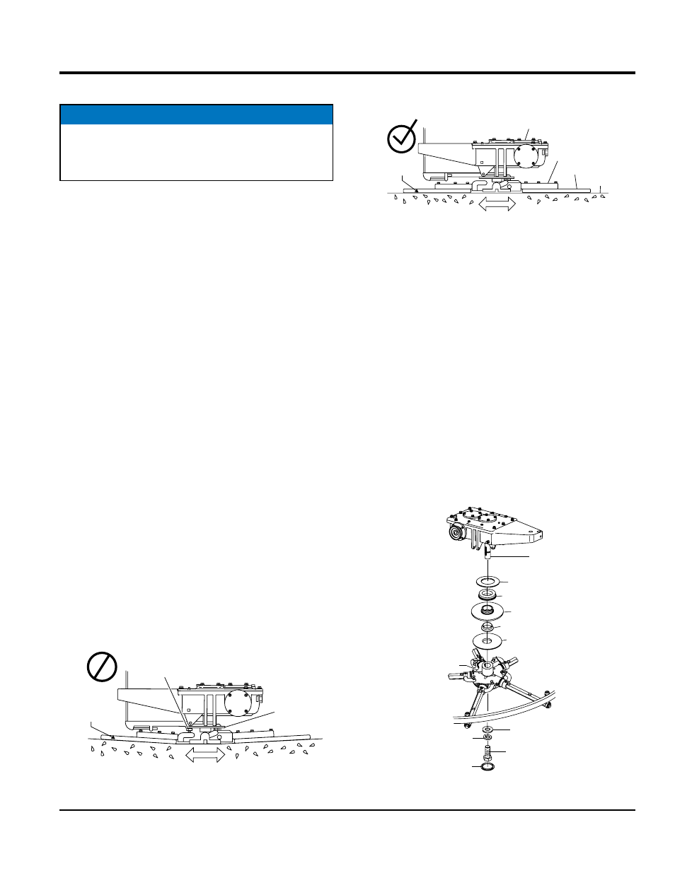
Figure 32 illustrates the “correct alignment” for a spider
plate (as shipped from the factory).
Figure 32. Correct Spider Plate Alignment
SpIDeR RemOvaL
Remove the spider assembly from the gearbox shaft as
follows:
1. Locate the cone point square head set screw (Figure
33) and attached jam nut found on the side of the
spider assembly.
2. Loosen the jam nut and cone point square head set
screw.
3. Carefully lift the upper trowel assembly off of the spider
assembly. A slight tap with a rubber mallet may be
necessary to dislodge the spider from the main shaft
of the gearbox.
4. For reassembly apply Blue Loctite #242 to the spider
retaining screw and torque to 130 ft.-lbs. (176 N.m)
Figure 33. Spider Removal
GEARBOX
SURFACE
CORRECT
ALIGNMENT
TROWEL
ARM
BLADE
MOUNTING BAR
Upper Wear Plate
Thrust Collar Bearing
Thrust Collar
Thrust Collar Bushing
Lower Wear Plate
Gearbox Shaft
Spider Plate
Retainer
Lock Washer
Retaining Screw
Plug