New machine setup – Multiquip HHNG5 User Manual
Page 21
HHNg5 RIDe-ON TROWeL • OpeRaTION maNuaL — Rev. #0 (07/16/13) — page 21
nEw MAchInE SEtUP
The purpose of this section is to assist the user in setting
up a
NEw trowel. If your trowel is already assembled, (seat,
handles, knobs and battery), this section can be skipped.
Before packaging and shipping, the this ride-on power
trowel was run and tested at the factory. If there are
problems, please let us know.
CONTROL HaNDLe aSSemBLy
The steering control handles are not attached to the
trowel's two lower handles at the time of shipment. To
attach the steering control handles to the two lower handle
assemblies, perform the following:
1. Remove the bolts from the plastic bag tied to the
control towers.
2. Remove all protective wrapping and straps from the
control handles.
3. Slip the top (loose) piece into the base of the
corresponding handle, making sure to line up the holes.
4. Install the bolt through the lined up holes and tighten
the acorn nut onto the threaded end.
5. Pay close attention to any wires that may be inside
the control handles.
dO NOT pinch or cut any wires
during installation.
6. Inside the plastic bag of parts are two knobs for the
pitch control tower cranks. Install these two knobs onto
the tower crank levers.
SeaT aSSemBLy
The seat is not installed on the trowel for shipping purposes.
To attach the seat perform the following:
1. Remove the seat from the protective wrapping.
2. Insert studs on bottom of seat through holes in the
mounting plate.
3. Install and tighten the provided nuts.
NOTICE
The new trowel cannot be placed into service until the
setup installation instructions are completed.
NOTICE
Some models are equipped with adjustable height
handles. Adjust the height by placing the bolt
through the set of holes that corresponds to the most
comfortable height.
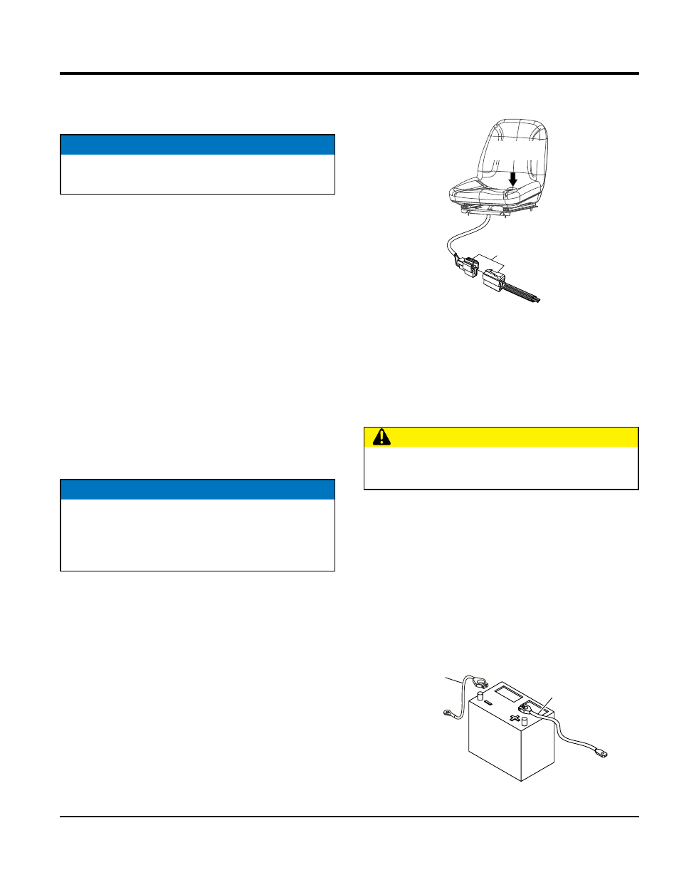
4. Connect the "Engine Stop Switch" (seat) cable to the
mating plug as shown in Figure 5
Figure 5. Engine Stop Switch (Seat)
BaTTeRy SeTup
This trowel was shipped with a wet charged battery. This
battery may need to be charged for a brief period of time
as per the manufacturer instructions.
To install the battery on the trowel, make sure that the
battery is well seated in the battery box. The positive cable,
normally red, is associated with the "+" symbol on the
battery. The negative cable, normally black, is associated
with the "-" symbol on the battery. See Figure 6. Connect
the positive cable to the positive terminal on the battery
first, then connect the negative cable to the negative
terminal. Close the plastic battery box cover and secure
the battery box.
Figure 6. Battery Cable Orientation
CONNECT
TO ENGINE
COIL
ENGINE STOP
SWITCH
CauTION
Use all safety precautions specified by the battery
manufacturer when working with the battery.
NEGATIVE
CABLE
(BLACK)
POSITIVE
CABLE
(RED)