Maintenance, Installing drive belt – Multiquip HHNG5 User Manual
Page 31
HHNg5 RIDe-ON TROWeL • OpeRaTION maNuaL — Rev. #0 (07/16/13) — page 31
MAIntEnAncE
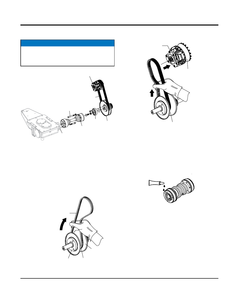
12. Disconnect the left-side CV Axle from the left-side gearbox
and the lower drive pulley coupler. See Figure 26.
Figure 26. Remove Left-Side CV Axle
13. If the belt is not being reused (recommended), CUT
the drive belt. Ensure all belt remnants are removed
from the pulleys.
INSTaLLINg DRIve BeLT
1. Place new CVT belt over the lower pulley. Squeeze the
belt (Figure 27) and pull the belt upwards and towards
the rear of the trowel. This will spread open the faces
of the lower drive pulley.
Figure 27. Holding Lower Pulley Open
NOTICE
Note that the 3 bolts securing the CV axle to the coupler
are shorter than those securing the CV axle to the
gearbox. Remember bolt orientation for reassembly.
LEFT-SIDE
GEARBOX
GEARBOX
COUPLER
CV AXLE
LOWER
DRIVE
PULLEY
COUPLER
CVT
BELT
UPPER DRIVE
PULLEY/CLUTCH
SHORTER
SCREWS (3)
CVT BELT
(P/N 23365)
MO
LOWER
PULLEY
VEABLE
FACE
FIXED
FACE
PULL UPWARDS
AND TOWARDS
REAR OF TROWEL
2. Place free end of CVT belt (Figure 28) into upper
pulley grooves.
Figure 28. Upper Pulley Belt Installation
3. Apply a thin coat of RVT silicone to mating surfaces
ofthe CV-joint (Figure 29) and left-side gearbox coupler.
Figure 29. Applying RTF Silicone
4. Reconnect the CV-joint to the left-side geaxbox coupler.
5. Re-install drive belt guard onto frame. Secure with
retaining screws (4).
CLUTCH
UPPER
PULLEY
LOWER
PULLEY
APPLY SILICONE
TO CV-JOINT
MATING SURFACES
RTV
SILICONE