Maintenance, Trowel arm adjustment – Multiquip HHN34TVD User Manual
Page 40
page 40 — HHN34TVD RIDe-ON TROWeL • OpeRaTION maNuaL — ReV. #2 (01/10/11)
Figure 42. Checking Trowel Arm Flatness
3. Next, check the clearance between the round shaft and
the test surface as one of the flat hex sections of the
arm rests on the test surface. Rotate the arm to each
of the flat hex sections and check the clearance of the
round shaft. Use a feeler gauge of .005" (0.127 mm).
Each section should have the same clearance between
the round of the trowel arm shaft and the test surface.
4. If the trowel arm is found to be uneven or bent, replace
the trowel arm.
TROWeL aRm aDJuSTmeNT
Shown in (Figure 43) is the adjustment fixture with a trowel
arm inserted. As each trowel arm is locked into the fixture,
the arm bolt is adjusted to where it contacts a stop on the
fixture. This will consistently adjust all of the trowel arms,
keeping the finisher as flat and evenly pitched as possible.
1. Locate the trowel arm adjustment tool P/N 9177.
Figure 43. Trowel Arm Adjustment Tool Side View
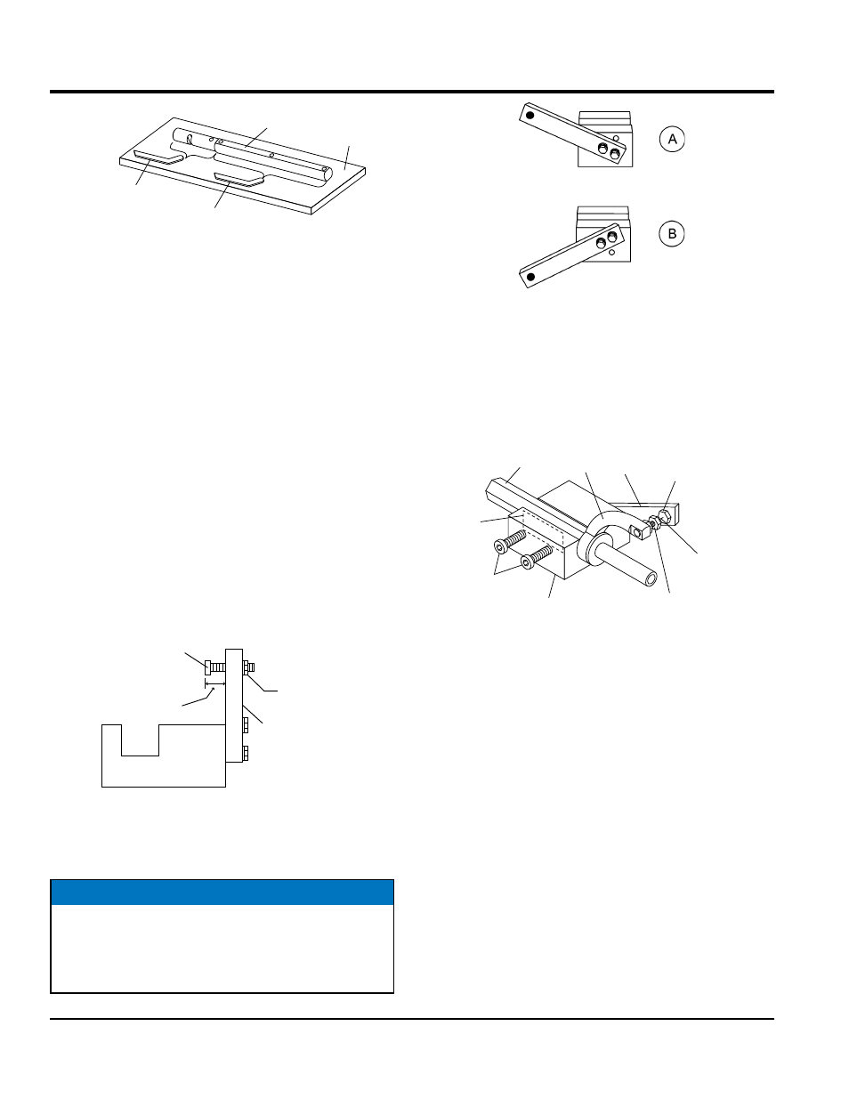
2. Ensure the fixture arm is in the proper setting (up or down)
for your trowel arm rotation as shown in Figure 44.
TROWEL
ARM
FLAT
TEST
SURFACE
FEELER GAUGE
(.004 in./0.10 mm)
FEELER GAUGE
(.005 in./0.127 mm)
ADJUSTMENT
BOLT
“DISTANCE”
LOCKING
NUT
FIXTURE
ARM
SIDE VIEW
NOTICE
Arms with CLOCK-WISE blade rotation use the fixture arm
in the UP position (Figure 44, A). Arms with COUNTER
CLOCK-WISE blade rotation use the fixture with the fixture
arm in the DOWN position (Figure 44, B).
Maintenance
Figure 44. Trowel Arm Adjustment Setup
3. Unscrew the locking bolts on the adjustment tool and
place the trowel arm into the fixture channel as shown
in Figure 45. A thin shim may be required to cover the
blade holes on the trowel arm. Make sure to align the
trowel adjustment bolt with the fixture adjustment bolt.
Figure 45. Trowel Arm Adjustment Fixture
Components
4. Use an allen wrench to tighten the locking bolts
securing the trowel arm in place.
5. Adjust the bolt “distance” shown in Figure 45to match
one of the arms. The other arms will be adjusted to
match this distance.
6. Loosen the locking nut on the trowel arm lever, then
turn the trowel arm adjusting bolt until it barely touches
(.010") the fixture adjusting bolt.
7. Once the correct adjustment is made, tighten the lock
nut on the trowel arm to lock in place.
8. Loosen locking nuts on the adjustment fixture, and
remove trowel arm.
9. Repeat steps for the remaining trowel arms.
ARM
TROWEL
ARM
LEVER
ADJUSTMENT
BOLT
ADJUSTMENT
BOLT
FIXTURE
ARM
DISTANCE =
.010 in.
TROWEL ARM
ADJUSTMENT
FIXTURE
LOCKING
BOLTS
SHIM