Components – Multiquip HHN34TVD User Manual
Page 18
page 18 — HHN34TVD RIDe-ON TROWeL • OpeRaTION maNuaL — ReV. #2 (01/10/11)
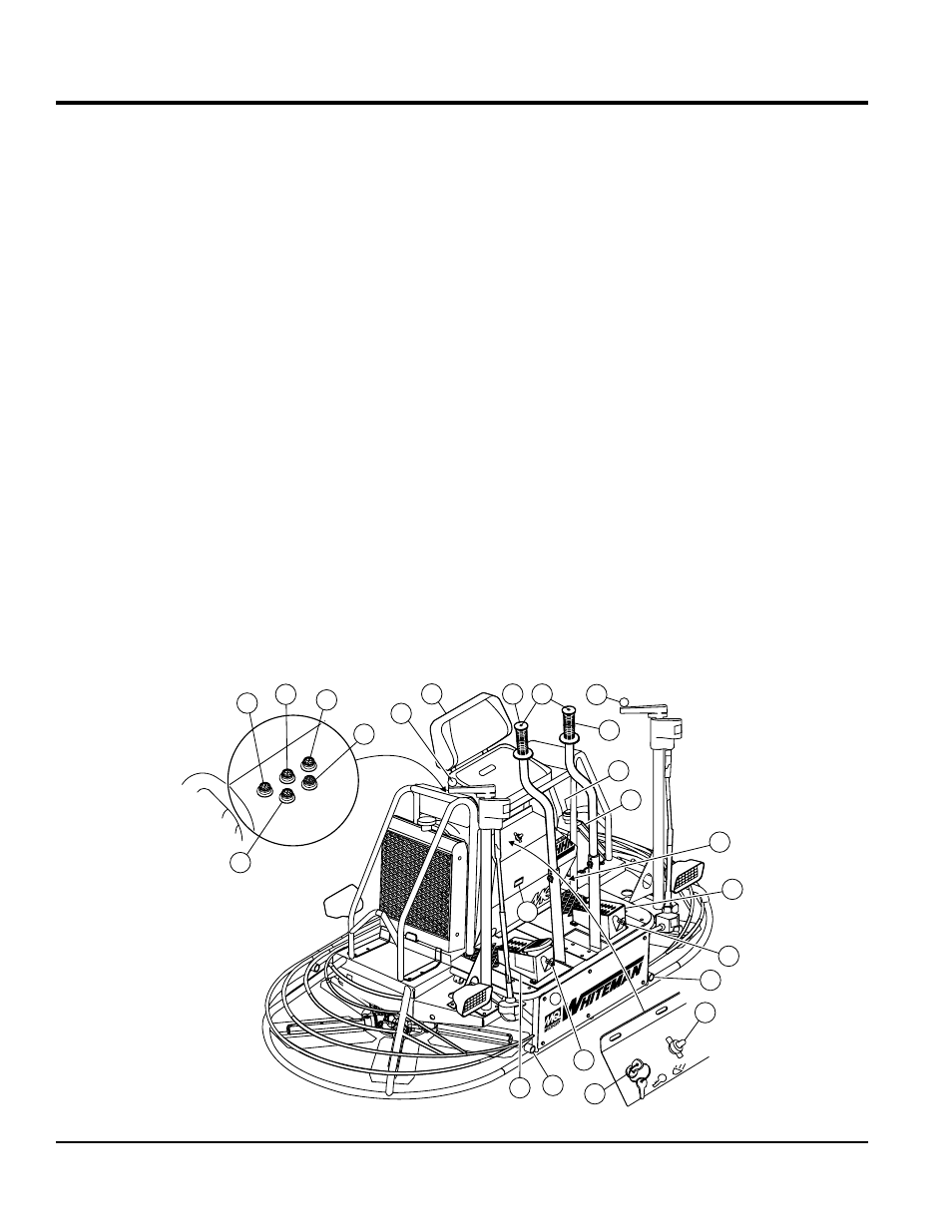
cOMpOnentS
1.
Seat — Provides comfortable position for operation of the
trowel. Engine will not start unless operator is seated. Seat
is adjustable, fore and aft for operator comfort.
2.
Steering Control Lever (right side) — Allows the unit
to move in either a forward, reverse left or right direction.
3.
Retardant Spray Control Buttons — When pressed
allows retardant spray to flow through the spray nozzle
located at the front of the machine.
4.
Twin pitch Control (Right) — Adjusts the blade pitch
for right side of the trowel. Turn the crank as marked
on its top surface to increase or decrease blade pitch.
5.
Twin pitch Control (Left) — Adjusts the blade pitch
for left side of the trowel. Turn the crank as marked
on its top surface to increase or decrease blade pitch.
6.
Steering Control Lever (left side) — Allows the unit to
move in either a forward, reverse left or right direction.
7.
Light Switch — When activated, turns on four halogen
lights. Lights offer better visibility when working indoors.
8.
Ignition Switch — With key inserted turn clockwise
to start engine.
9.
Oil Indicator Light — Lights red when oil pressure is low.
10.
Water Indicator Light — Lights red when water
temperature is high.
11.
Charge Indicator — Lights red when electrical system
is not charging properly.
12.
Hour meter — Indicates number of hours the key
switch is in the "ON" position.
13.
preheat Light — Lights blue when glow plugs are
energized.
14.
Fuel gauge/Filler Cap — Indicates the amount of fuel
in the fuel tank. Remove this cap to add fuel.
15.
Fuel Tank — Holds 5 gallons of fuel.
16.
Spare Belt Carrier — Contains a spare belt. Belt is
used on the drive pulley.
17.
Left Foot Riser — Operator foot rest pedal.
18.
Spray Nozzles — Spray nozzle for retardant.
19.
Right Foot pedal — Controls blade speed. Slow blade
speed is accomplished by slightly depressing the foot
pedal. Maximum blade speed is accomplished by fully
depressing the foot pedal.
20.
ez- mover Boss — Front -side insertion point for EZ Mover.
Used when the transporting of the trowel is required.
CHG
W
ATE
R
OI
L
GLOW
PLUG
S
FUEL
FI
LT
ER
S
E
R
I E
S
3
2
4
1
8
18
17
16
14
15
18
7
9
10
11
13
21
6
5
12
19
20
20
Figure 2. HHN34TVD Components (Front)