Maintenance, Spider removal, Trowel blade removal – Multiquip HHN34TVD User Manual
Page 38
page 38 — HHN34TVD RIDe-ON TROWeL • OpeRaTION maNuaL — ReV. #2 (01/10/11)
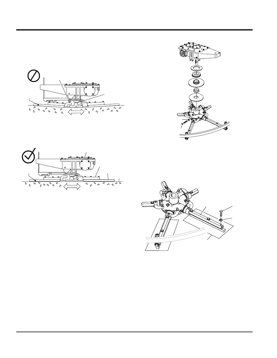
Figure 34 illustrates “incorrect alignment,” worn spider
bushings or bent trowel arms. Check that the adjustment
bolt is barely touching (0.10" max. clearance) lower wear
plate. All alignment bolts should be spaced the same
distance from the lower wear plate.
Figure 34. Incorrect Spider Plate Alignment
Figure 35 illustrates the “correct alignment ” for a spider
plate (as shipped from the factory).
Figure 35. Correct Spider Plate Alignment
SpIDeR RemOVaL
Remove the spider assembly from the gearbox shaft as
follows:
1. Locate the cone point square head set screw (Figure
36) and attached jam nut found on the side of the
spider assembly.
2. Loosen the jam nut and cone point square head set
screw.
3. Carefully lift the upper trowel assembly off of the spider
assembly. A slight tap with a rubber mallet may be
necessary to dislodge the spider from the main shaft
of the gearbox.
ADJUSTMENT BOLT
LOWER
WEAR PLATE
SURFACE
“DISHED”
EFFECT ON
FINISHED
CONCRETE
GEARBOX
SURFACE
CORRECT
ALIGNMENT
TROWEL
ARM
BLADE
MOUNTING BAR
Maintenance
Figure 36. Spider Removal
TROWeL BLaDe RemOVaL
Remove the trowel blades by removing the three hex head
bolts (Figure 37) from the trowel arm. Set blades aside.
Figure 37. Trowel Blade Removal
JAM NUT
GEARBOX
SET SCREW
TROWEL
ARM
TROWEL
BLADE
HEX HEAD
BOLT
LOCK
WASHER