Wrs-5200 — machine controls – Multiquip WRS5200 User Manual
Page 22
PAGE 22 — WRS 5200 RIDE-ON ROLLER SCREED — PARTS MANUAL — REV. #2 (08/09/02)
WRS-5200 — MACHINE CONTROLS
Operators Position)
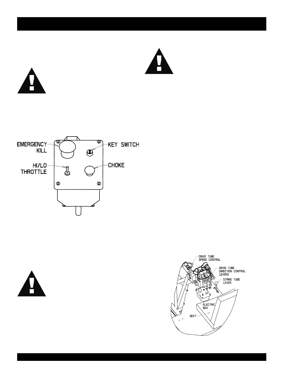
1. Electric Box (Figure 12).
WARNING!
Your Whiteman Ride-On Roller Screed is equipped with a
safety emergency kill switch. Note: It is provided for opera-
tor safety and injury may result if it is disabled, disconnected
or improperly maintained.
The key switch, shown in Figure 12, is located to the right of
the kill switch. The key switch should not work if the kill
switch is in the down “Down” position.
Figure 12. Electric Box
WARNING!
Below the kill switch is the “High/Low” toggle switch. This
throttle switch has only two positions.
The choke button is to the right of the Hi/Low switch. To
activate this switch, you must hold it down.
2. Light Switch.
The light switch is located on the fuse box which is mounted
on the radiator end of the power unit.
3. Drive Tube Speed Control Lever (Figure 13).
Located on the far left, above the electric box, this long
handle controls the variable speed of the drive tubes. This
lever should be in the “Straight Up” position when starting
the engine.
4. Drive Tube Direction Control Levers (Figure 13).
Located in the center, these two levers control the direction
of travel for the drive tubes. They are independent of each
other, so one end can travel forward while the other travels
back. Using the levers in this way lets you steer the roller
screed.
Figure 13. Operator Controls
THE THROTTLE CONTROL CANNOT BE
USED TO STOP THE ENGINE.
THE THROTTLE CONTROL CAN-
NOT BE USED TO STOP THE EN-
GINE.
NEVER DISABLE OR DISCONNECT THE
EMERGENCY KILL SWITCH.