How to connect the cable, How to connect the cable 38 – MTS Axial Extensometers User Manual
Page 38
Configuration
38
How to Connect the Cable
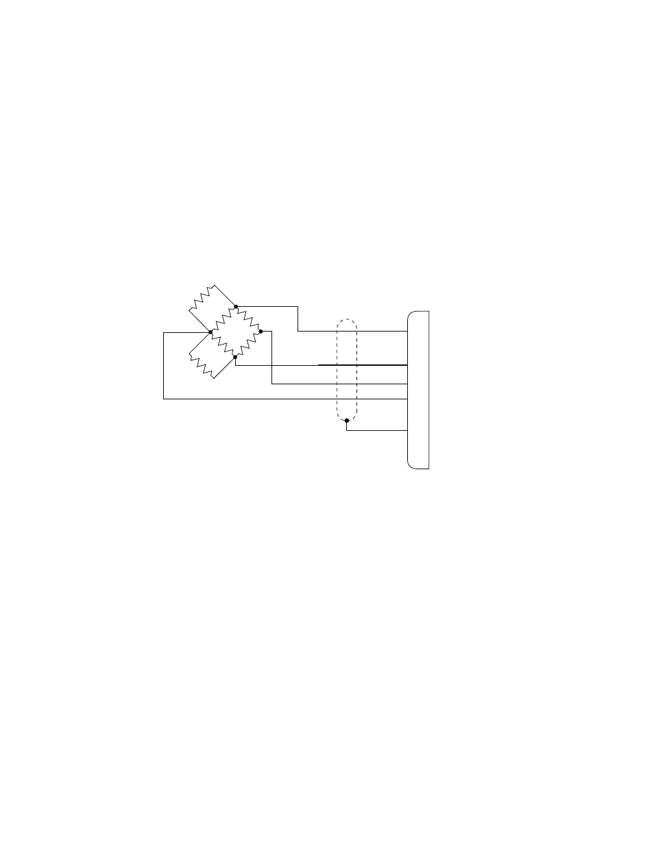
The extensometer cable connects to the system controller via an
extension cable. The extensometer has a small cable and connector built
in. An extension cable is installed between the extensometer connector
and the system controller. Ensure that the extensometer is connected to
the appropriate controller connector. The controller connector must be
associated with a DC conditioning circuit. The following figure shows
the circuitry and connector pin assignments from the extensometer.
Extensometer Electrical Connections
The following information pertains to your system controller:
•
The location of the shunt resistors differs with each controller.
See your controller manual for more information about the
shunt calibration resistors.
•
The location of the bridge balancing circuitry differs with
each controller. See your controller manual for more
information about the bridge balancing circuitry.
•
Extensometer connector = PT01A-10-6P (or equivalent)
•
Mating connector = PT06A-10-6S
1. Attach the plastic connector holder, provided with the
extensometer, to the load unit column.
RED
GRN
BLK
WHT
+Excitation
-Excitation
A
D
C
B
F
E
-Output
+Output
Shield
Shunt
R1
Shunt
R2
1
2
3
4
350
W
Note
The location of the shunt cal
resisters depends on the
controller being used.