MTS Acumen Electrodynamic Test Area Enclosure User Manual
Page 11
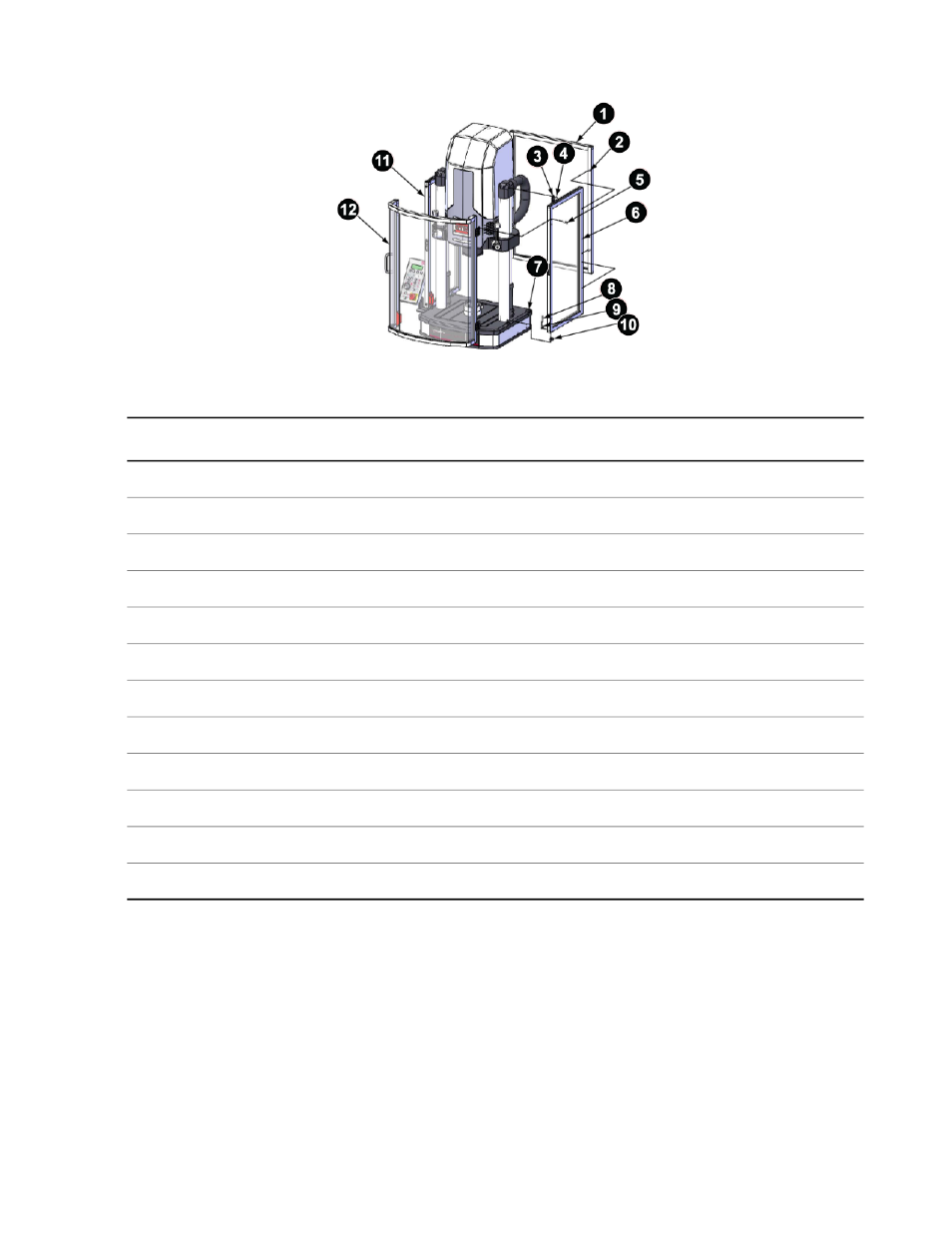
Test Area Enclosure
Description
Item
Rear panel assembly
1
M6 x 1 mm x 35 mm socket low head screw
2
Top bracket
3
M6 x 1.00 mm x 12 mm buttonhead cap screw
4
M6 x 25MM x 12 mm flathead screw
5
Left side panel assembly
6
Foot mount
7
M5 X 35MM socket head screw, M5 butt fastener
8
M5 C'Bore butt fastener
9
Foot mount
10
Right side panel assembly
11
Front door assembly
12
1. Raise the crosshead.
2. Put two foot mounts (items 7 and 10) on the frame in the provided machined indents.
3. Put a M6 x 1.00 mm x 12mm buttonhead cap screw (item 4) for the top bracket on the baseplate.
Once the side panel is in place and before you tighten down the bottom screws, it makes installation easier
to secure the top side panel bracket to the frame to help hold the side panel in position while you tighten
the bottom screws to secure the side pane to the frame base. This step puts the top bracket screw where
you can reach it when the time comes.
MTS Acumen™ Electrodynamic Test System 11
Test Area Enclosure Installation
- Series 111 Accumulator (40 pages)
- Series 249G2 Swivels (34 pages)
- Series 201 Actuators (40 pages)
- Series 215 Rotary Actuator (68 pages)
- Series 242 Actuators (40 pages)
- Series 244 Actuators (68 pages)
- Series 247 Actuators (40 pages)
- Series 248 Actuators (46 pages)
- 709 Alignment System (158 pages)
- Series 609 Alignment Fixture (70 pages)
- 494 Controller Hardware FT 40 (344 pages)
- ReNew Technical Reference (50 pages)
- DCPD Measurement System (46 pages)
- Bionix EnviroBath (40 pages)
- FGW900 High-temperature Furnace (38 pages)
- Model 409.83 Temperature Controller (40 pages)
- Series 651 Environmental Chambers (30 pages)
- Series 653 High-Temperature Furnaces (38 pages)
- Series 658 Environmental Chamber (24 pages)
- Series FEC Environmental Chamber (48 pages)
- Model 685.53 Grip Control Module (24 pages)
- Series 685 Hydraulic Grip Supply (48 pages)
- Bend Fixture-10 kN (2 pages)
- Grip-Manual Bend Fixture-100 kN (2 pages)
- Grip-Manual Bollard-2 kN (2 pages)
- Grip-Manual Bollard-500 N (2 pages)
- Compression Platen-100 kN-100mm (2 pages)
- Compression Platen-100 kN-150mm (2 pages)
- Compression Platen-100 kN-200mm (2 pages)
- Compression Platen-20 kN (2 pages)
- Compression Platen-20 kN-100mm (2 pages)
- Compression Platen-20 kN-200mm (2 pages)
- Compression Platen-20 kN-SST (2 pages)
- Compression Platen-500 N FYC502A (2 pages)
- Compression Platen-500 N FYB502A (2 pages)
- Compression Platen-500 N-50mm (2 pages)
- Grip-Pneumatic Vise-Style-1 kN (2 pages)
- Pneumatic Bollard-500 N (2 pages)
- Scissor-Style-2 kN (2 pages)
- Scissor-Style-5 kN (2 pages)
- Screw-Style-5 kN (2 pages)
- Screw-Style-5 kN-SST (2 pages)
- Bend Fixture-1000 kN (2 pages)
- Bend Fixture-300 kN (2 pages)
- Bolt Grips (32 pages)