Section 5 theory of operation, 1 hydraulic operation – MTS Hydraulic Power Unit Model 506-92 User Manual
Page 38
Theory of Operation 5-1
Section 5
Theory of Operation
This section describes the hydraulic and electrical operation of Model
506.82/.92 Hydraulic Power Unit (HPU).
5.1
Hydraulic Operation
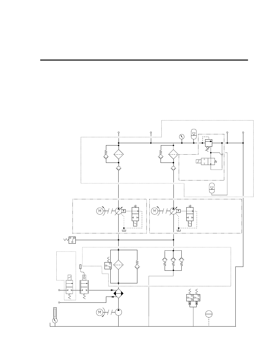
The figure below is a block diagram of the HPU hydraulic operation.
3 micron
fine filter
filter bypass
50 psi
(0.34 MPa)
supercharge
pump
fluid level/temperature gage
water out
standard
water
regulating
valve
water in
optional
water
shut-off
solenoid
valve
pressure
-24 JIC
pressure
-32 4 bolt
pressure
gage
pressure
accumulator
backup relief valve
3500 psi (25 MPa)
return
-24 JIC
return
-32 4 bolt
slow turn-on
accumulator
outlet filter
10 micron
outlet filter
10 micron
main manifold
assembly
check valve
check valve
pump 1 – compensator
set at 3000 psi (21 MPa)
pump 2 – compensator
set at 3050 psi (21 MPa)
low inlet pressure switch
supercharge relief valve –
cracks at 30 psi (0.2 MPa)
filter pressure
switch
35 psi
(0.24 MPa)
supercharge and
manifold filter
heat
exchanger
water shut-off solenoid
valve switch – 100
°
F
(38
°
C) rising
over-temperature
switch – 140
°
F
(60
°
C) rising
low fluid level
float switch
3Sol
24 Vdc
2Sol
1Sol
1PS
2PS
24 Vdc
20 psi (0.14 MPa)
1FS
VW-C038
4Sol
Figure 5-1. Hydraulic Block Diagram