1 transformer wiring, 4 . 2 . 1 transformer wiring – MTS Hydraulic Power Unit Model 506-92 User Manual
Page 35
Installation 4-4
4 . 2 . 1
Transformer Wiring
One of two types of transformers is installed in the starter assembly. Check
the wiring configuration of the transformer before applying ac power to
the HPU.
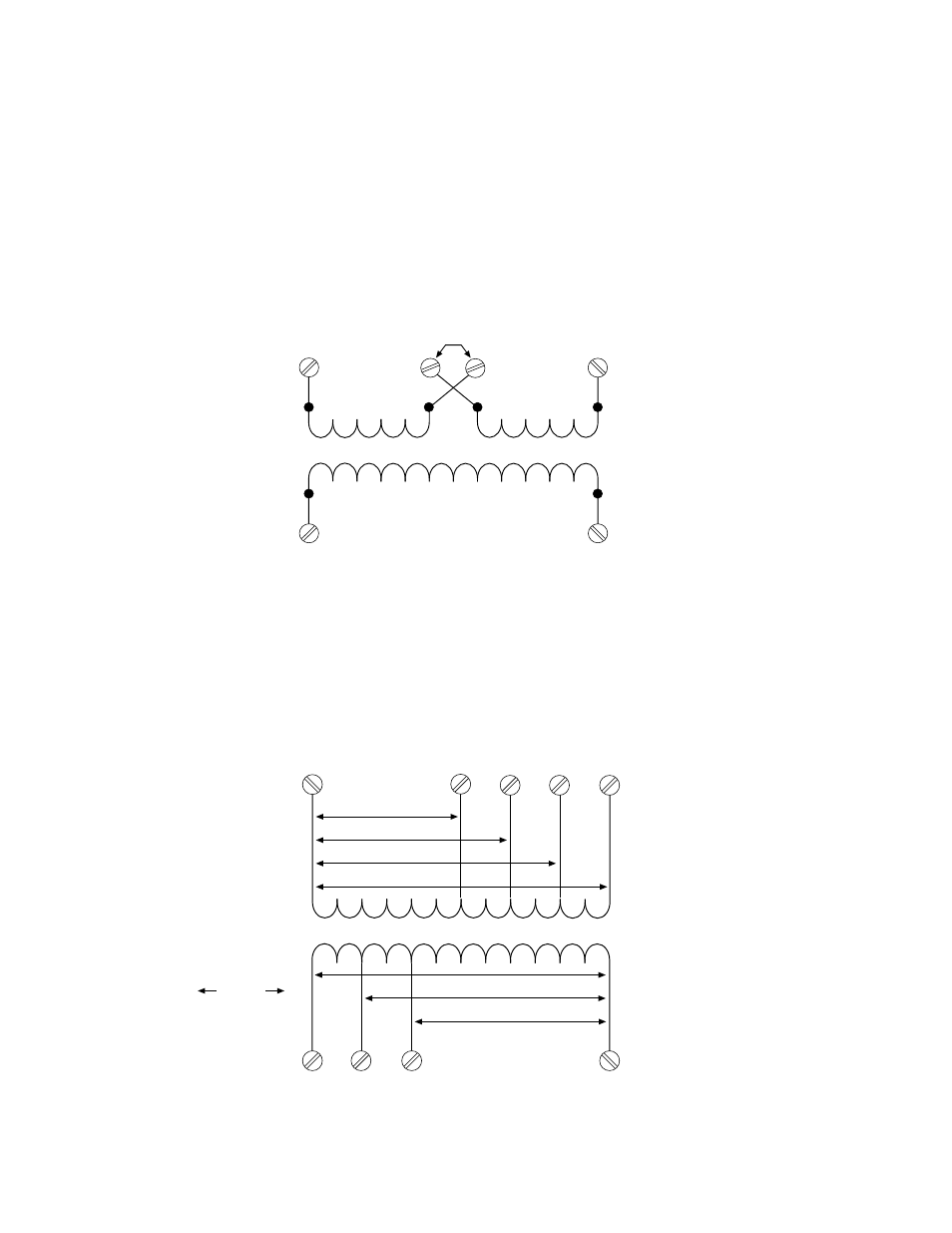
Standard
transformer wiring
Figure 4-4 shows the jumper wiring required on a standard transformer for source voltages of 460.
H1
X2
H2
X1
H3
460 Vac
H4
VW-C036
Figure 4-4. Standard Transformer Wiring Configuration
Optional
transformer wiring
An optional multi-tap transformer may be used for source voltages other
than 230 Vac and 460 Vac. The following figure shows the typical wiring
required for various voltages. Source voltages are applied to terminals H1
through H5 as shown. An output voltage is tapped from terminals X1
through X4. Check the output voltage with a voltmeter. It should be 110
Vac for systems using 50 Hz power and 115 to 120 Vac for systems with
60 Hz.
X4
VW-C037
X3
X2
X1
H4
H5
H3
H2
H1
208/220/230/240 Vac
380/400/416 Vac
440/460/480 Vac
500/550/575/600 Vac
110/120/125/130 Vac
100/110/115/120 Vac
85/91/99 Vac
jumper
Figure 4-5. Typical Multi-Tap Transformer Wiring Configuration