Sideload calculation procedure, Sideload calculation procedure 33 – MTS Series 242 Actuators User Manual
Page 33
Sideload Calculation Procedure
Series 242 Actuator Product Information
Operation
33
•
Minimum allowable sideload frequency
Sideload Calculation Procedure
The following procedure provides you with information to determine the
suitability of a particular actuator model for tests requiring nonaxial loading.
Some of the constants used in this procedure are defined in the steps and others
are listed in the following table.
Note
The examples included in this procedure assume that the values of F
and P are measured in pounds force and that B, C, and S (stroke) are
measured in inches.
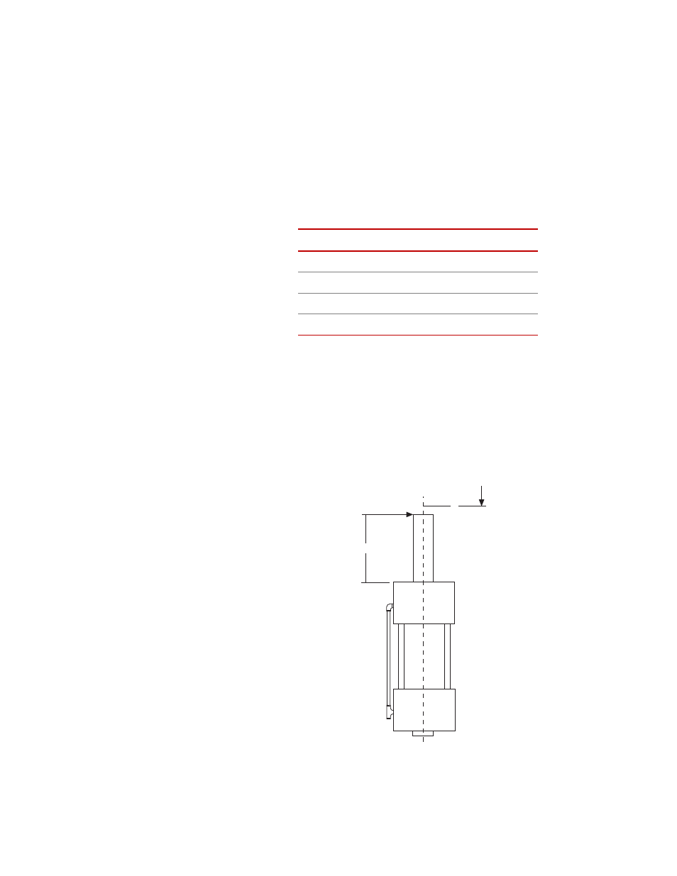
1. Determine the magnitude of nonaxial loads F and P and the point of
application of these loads (B and C respectively). These parameters are
dependent on the test setup configuration. If any parameter is variable
during the test, use the maximum values.
2. Calculate the actuator bearing load (L) using the following formula:
Sideload Constants
S
TROKE
(S)
B
EARING
S
PACING
(A)
25.4 mm (1 in)
96.8 mm (3.82 in)
50.8 mm (2 in)
96.8 mm (3.82 in)
76.2 mm (3 in)
109.5 mm (4.31 in)
101.6 mm (4 in)
109.5 mm (4.31 in)
B
F
P
C
Sideload Forces