T13-b s – Metal Sales TDR-6 User Manual
Page 13
PI/D-13
I
ndustrIal
r
Ib
/ d
eep
r
Ib
s
erIes
© Metal Sales Manufacturing Corporation/ Subject to change without notice/ Effective Date 9/11
800.406.7387 (Corporate Office) • www.metalsales.us.com
T13-b s
eCTion
P
roPerTies
ALLOWABLE UNIFORM LIVE LOADS PSF
(3 or More Equal Spans)
5’ 6’ 7’ 8’ 10’ 12’ 5’ 6’ 7’ 8’ 10’ 12’
SECTION PROPERTIES
Bottom in Compression
Width
(in.)
Yield
KSI
30”
50
30”
50
30”
33
30”
33
24
Ga.
22
20
18
Sxx
In
3
/ft
Ixx
In
4
/ft
Weight
PSF
1.58
2.06
2.41
3.15
Top in Compression
Sxx
In
3
/ft
Ixx
In
4
/ft
0.4032
0.1774
0.3156
0.1697 137 99 75 58 38 27 189 137 104 81 53 37
0.6224
0.2926
0.4804
0.2794 242 172 128 99 64 45 335 238 178 137 89 62
0.8760
0.4399
0.6320
0.3880 230 162 120 92 59 41 345 243 180 138 89 62
1.2360
0.6364
0.9040
0.5836 347 244 180 138 89 62 502 353 261 201 129 90
Inward (Gravity / Deflection)
Load
Outward Uplift (Stress)
Load
1. Theoretical section properties have been calculated per AISI 2001 “Specification for the Design of Cold-formed Steel Structural Members.” Ixx and Sxx are
effective section properties for deflection and bending.
2. Allowable load is calculated in accordance with AISI 2001 specifications considering bending, shear, combined bending and shear, deflection, and applicable
testing when available. Allowable load considers the worst case of 3 and 4 equal span conditions. Allowable load does not address web crippling or
fasteners/support connection and panel weight is not considered.
3. Deflection consideration is limited by a maximum deflection ratio of L/180 of span.
4. Allowable loads do not include a 1/3 stress increase in uplift.
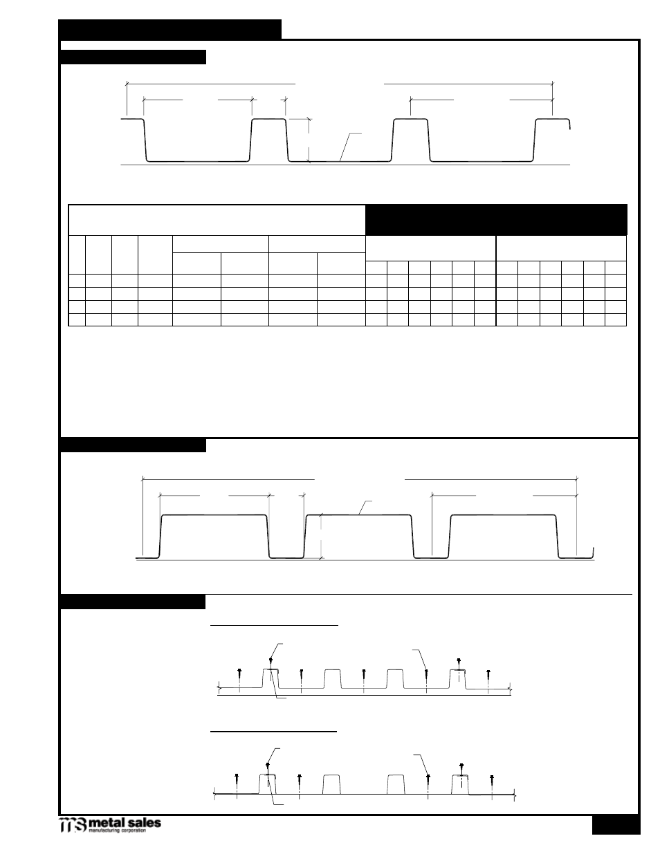
C
30" Coverage
10" Pitch
3"
2
3
/
8
"
7
5
/
8
"
C
30" Coverage
10" Pitch
3"
2
3
/
8
"
7
5
/
8
"
Fastening Pattern (Ends)
Fastening Pattern (Field)
1
/
4
"-14 x
7
/
8
" Stitch (roof only)
Tape Sealant (roof only)
#12-14 x 1
1
/
4
" SD
#12-14 x 1
1
/
4
" SD
Tape Sealant (roof only)
1
/
4
"-14 x
7
/
8
" Stitch (roof only)
FASTENING PATTERNS
ROOF PANEL PROFILE
WALL PANEL PROFILE