T13-a s – Metal Sales TDR-6 User Manual
Page 12
PI/D-12
© Metal Sales Manufacturing Corporation/ Subject to change without notice/ Effective Date 9/11
800.406.7387 (Corporate Office) • www.metalsales.us.com
I
ndustrIal
r
Ib
/ d
eep
r
Ib
s
erIes
T13-a s
eCTion
P
roPerTies
ALLOWABLE UNIFORM LOADS PSF
(3 or More Equal Spans)
5’ 6’ 7’ 8’ 10’ 12’ 5’ 6’ 7’ 8’ 10’ 12’
SECTION PROPERTIES
Bottom in Compression
Width
(in.)
Yield
KSI
24”
50
24”
50
24”
33
24”
33
24
Ga.
22
20
18
Sxx
In
3
/ft
Ixx
In
4
/ft
Weight
PSF
1.78
2.35
2.79
3.67
Top in Compression
Sxx
In
3
/ft
Ixx
In
4
/ft
0.5390
0.3037
0.5785
0.3264 261 189 143 112 73 51 248 179 134 105 68 48
0.7795
0.4620
0.8325
0.4934 430 305 227 175 113 79 406 287 213 164 106 74
1.0060
0.6235
1.0660
0.6587 391 274 203 156 101 70 371 261 193 148 95 66
1.4100
0.9068
1.4750
0.9404 557 392 290 223 144 100 539 378 280 215 138 95
Inward
Load
Outward
Load
1. Theoretical section properties have been calculated per AISI 2001. “Specifications for the Design of Cold-formed Steel Structural
Members.” Ixx and Sxx are effective section properties for deflection and bending.
2. Allowable load is calculated in accordance with AISI 2001 specifications considering bending, shear, combined bending and shear and
deflection. Allowable load considers both 3 or more equal span conditions. Allowable load does not address web crippling or
fasteners/support connection. Panel weight is not considered.
3. Deflection consideration is limited by a maximum deflection ratio of L/180 of span.
4. Allowable loads do not include a 1/3 stress increase in uplift.
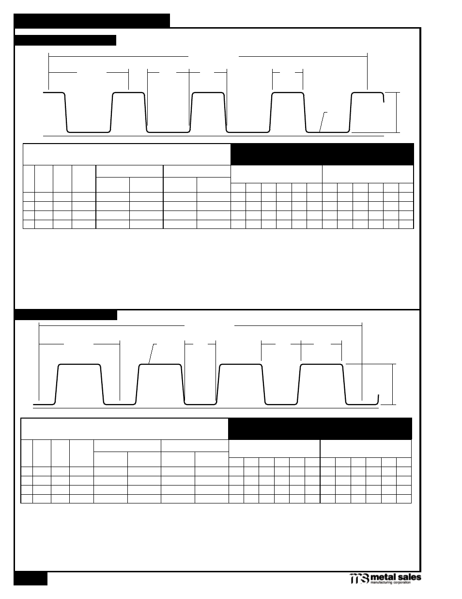
C
24" Coverage
3"
6" Pitch
2
3
/
8
"
3
1
/
8
"
2
7
/
8
"
ALLOWABLE UNIFORM LOADS PSF
(3 or More Equal Spans)
5’ 6’ 7’ 8’ 10’ 12’ 5’ 6’ 7’ 8’ 10’ 12’
SECTION PROPERTIES
Bottom in Compression
Width
(in.)
Yield
KSI
24”
50
24”
50
24”
33
24”
33
24
Ga.
22
20
18
Sxx
In
3
/ft
Ixx
In
4
/ft
Weight
PSF
1.78
2.35
2.79
3.67
Top in Compression
Sxx
In
3
/ft
Ixx
In
4
/ft
0.5785
0.3264
0.5390
0.3037 248 179 134 105 68 48 261 189 143 112 73 51
0.8325
0.4934
0.7795
0.4620 406 287 213 164 106 74 430 305 227 175 113 79
0.0660
0.6587
1.0060
0.6235 371 261 193 148 95 66 391 274 203 156 101 70
1.4750
0.9404
1.4100
0.9068 539 378 280 215 138 96 557 392 290 223 144 100
Inward
Load
Outward / Uplift
Load
1. Theoretical section properties have been calculated per AISI 2001. “Specifications for the Design of Cold-formed Steel Structural
Members.” Ixx and Sxx are effective section properties for deflection and bending.
2. Allowable load is calculated in accordance with AISI 2001 specifications considering bending, shear, combined bending and shear and
deflection. Allowable load considers both 3 or more equal span conditions. Allowable load does not address web crippling or
fasteners/support connection. Panel weight is not considered.
3. Deflection consideration is limited by a maximum deflection ratio of L/180 of span.
4. Allowable loads do not include a 1/3 stress increase in uplift.
C
24" Coverage
3"
6" Pitch
2
7
/
8
"
3
1
/
8
"
2
3
/
8
"
ROOF PANEL PROFILE
WALL PANEL PROFILE