Mayline Triple Base Only User Manual
Page 3
(3)
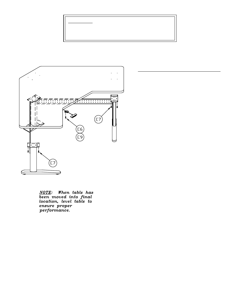
10. PRIOR TO ATTACHING WORKSURFACE:
Place the switch cord over the top of the Cross
Channel.
11. Align the holes in the Top with the holes in
the Mounting Plates and secure in place with
twelve #10 X 1 Screws (E7).
12. Align the holes in the Control Box (8) with the
holes in the underside of the Top and attach it
with four #10 x 3/4 Screws (E6).
13. Connect the cables to the columns. Connect
the 78.74 Cables (12) to the Outer Actuator
Columns. Connect the 39.37 Cable (11) to the
Corner Actuator Column.
14. Place the Memory Switch (9) in a
comfortable and accessible location on the
underside of the Top and attach it with two #6 x
5/8 Screws (E8).
15. Route the Actuator Column cables and the
Memory Switch cable away from moving
components and secure them in place with
Cable Clamps (E9) and Screws (E6).
ATTENTION:
MAYLINE includes screws for the installation of a Work
Surface with a minimal thickness of 1 inch (25.4mm).