Mayline Convert Rule to Above Board Attachmen User Manual
Mayline Hardware
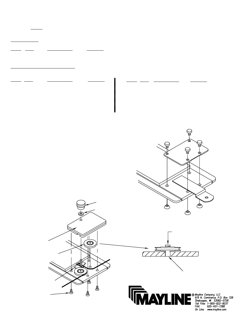
Fig. 1
INSTRUCTIONS TO CONVERT RULE TO
ABOVE-BOARD ATTACHMENT
REF # QTY. DESCRIPTION PART No.
E7 4 #6 x 1/2" Screw X37*
E8 8 #6 X 1/4" Screw X44S*
E9 2 #6 x 1" Screw X14*
E10 3 Knob K22*
E11 2 Brake Shoe Assembly A2123*
E12 1 Cable Clamp B9*
NOTE: Please count and inspect all pieces before disposing of any carton or packing materials.
COMPONENTS:
REF.# QTY. DESCRIPTION PART No.
1 CALL~~ Cable Coil CALL~~
2 2 Pulley Housing F314
HARDWARE BAG (PART No. A2297)
*for individual item, order that part number
REF # QTY. DESCRIPTION PART No.
E1 1 R.H. Corner Plate Assembly A2294*
E2 1 L.H. Corner Plate Assembly A2295*
E3 2 Stedge Stop F330*
E4 2 Side Guide B1003*
E5 4 Ball bearing Pulley P14*
E6 2 Washer W42*
Washer (E6)
Knob (E10)
1. Remove present end plates and sliding bars from end of
straightedges. (See Fig. 1)
2. Insert the two Ball bearing Pulleys (E5) into holes located
per Fig. 2 With knurled portion of stud in hole, push down until
shoulder is tight against blade.
3. Repeat for other end of Straightedge.
4. Install Cable Assembly. Refer to section "Instructions for
Restringing Mayline Straightedge".
5. Attach straightedge to board. Refer to section " Assembly
Instructions for Mounting Straightedge".
Ball bearing
Pulley (E5)
NOTE: Brake Shoe (E11)
located under cable
#6 x 1/4"
Screw (E8)
Pulley
Housing (2)
Fig. 2
Knurl End
of Pulley
Tap
When ordering components, specific color and/or size information may be required.
Contact a Mayline Customer Service Representative. 1-800-822-8037
CATALOG No.
7301A
7301B
7301C
(1)