Mayline Under-Board Rule Attachment User Manual
Mayline Hardware
NOTE: Please count and inspect all pieces before disposing of any carton or packing materials.
When ordering components, specific color and/or size information may be required.
Contact a Mayline Customer Service Representative. 1-800-822-8037
COMPONENTS:
REF. # QTY. DESCRIPTION PART No.
1 1 CABLE COIL ASSEMBLY CALL~~
2 1 UPPER RIGHT PULLEY A1085
3 1 UPPER LEFT PULLEY A1086
4 1 LOWER RIGHT PULLEY A1087
5 1 LOWER LEFT PULLEY A1088
6 2 ATTACHMENT CLAMP KIT A1089
HARDWARE BAG (PART No. A104)
*for individual item, order that part number
REF. # QTY. DESCRIPTION PART No.
E1 4 WASHER W26*
E2 8 #6 x 1/2 SCREW X37*
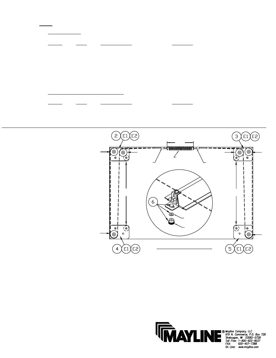
INSTALLATION INSTRUCTIONS
for UNDER-BOARD RULE ATTACHMENT
1. Attach the four pulley assembly
plates to the underside of the board.
Place single pulley units to the front
corners and double pulley units to the
rear corners as shown.
NOTE: When attaching to steel tops,
drill 1/8" holes to mount pulley assembly
plates. When this attachment is used
on a Mayline Steel End Cleat board,
place a Washer (E1) as a shim under
the inside corner of each pulley plate as
indicated by arrows "G".
2. Crimp Ring Terminal to one end of
cable. Do not twist or kink cable.
3. Startling from Top Center of board,
thread end of cable around pulley "A" to
front of board around pulley "B", then
back around pulley "C". Now cross the
board and thread around pulley "D",
then to front of board around pulley "E"
and back around pulley "F".
4. Connect Ring Terminal and cable to
spring. Slide 2nd Ring Terminal on
opposite end of cable and attach Ring
Terminal to other end of spring. Hold
Ring Terminal and pull cable until spring
is extended 1/2" to 3/4". Crimp terminal
in this position. Be sure that the cable
runs freely.
5. Place straightedge in position on board and fasten blade
clamps (shown upside down, Fig.1) to ends of straightedge
with knurled nuts. Adjust sliding bar to correct length and
tighten screws.
6. Loosen cable clamp screws on bottom of blade clamps
and place cable between washer and groove in blade
clamps, align straightedge and clamp cable by tightening
cable clamp screws. Straightedge can be removed from
blade and replaced without changing alignment by simply
removing knurled nuts.
UNDERSIDE OF BOARD
Fig. 1
D
F
G
E
G
A
C
B
CATALOG No.
7302A
7302B
7302C
~~Denotes Size
SPRING
SPRING LENGTH
NOT TO EXCEED
3.50
WASHER
KNOB
RING
TERMINAL
RING
TERMINAL