Center leg assembly – Mayline Maytrix Frame User Manual
Page 3
NOTE:
It is a MAYLINE recommendation
that NEVER MORE THAN TWO
FRAMES be joined together utilizing
the Center Leg Support (5).
COMPONENTS: PRODUCT 350212
REF.# QTY. DESCRIPTION PART No.
5 1 CENTER LEG SUPPORT A4437**
HARDWARE BAG (PART No. A4360)
*for individual item, order that part number
REF. # QTY. DESCRIPTION PART No.
E9 1 GLIDE Q471*
E10 4 5/16-18 HEX NUT T27*
E11 4 5/16-18 X 2 3/4 SCREW X316*
When ordering components, specific color and/or size information may be required.
Contact a Mayline Customer Service Representative. 1-800-822-8037
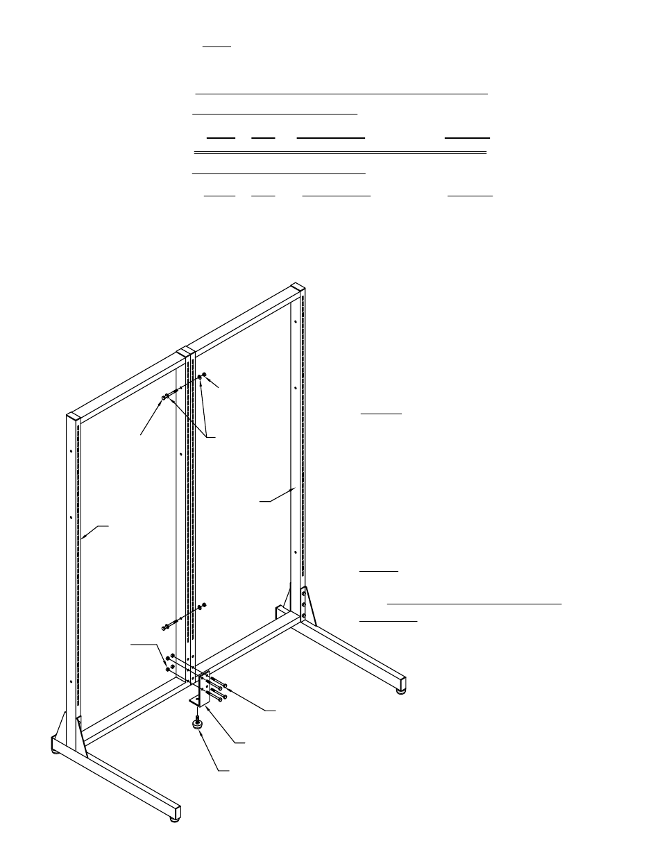
CENTER LEG ASSEMBLY
ASSEMBLY NOTE: Do not tighten bolts until
all components are assembled.
5. Bolt Frames (1) together using 1/4-20 x 2
1/2 Screws (E4), Washers (E3) and 1/4-20 Hex
Nuts (E2) included with frames.
NOTE: Use the uppermost set of holes when
attaching frames of equal height.
6. Attach Center Support (5) with 5/16-18 x 2
3/4 Screws (E11) and 5/16-18 Hex Nuts (E10).
7. TIGHTEN ALL BOLTS SECURELY.
8. Level Frames by adjusting Glides (E2 and
E13).
** Denotes Color Code
Frame (1)
Center Support (5)
Glide (E9)
5/16 -18
Hex Nuts (E10)
5/16 -18 x 2 3/4
Screws (E11)
Washer (E3)
1/4-20
Hex Nuts (E2)
1/4 -20 x 2 1/2
Screws (E4)
Frame (1)
NOTE: Please count and inspect all pieces before disposing
of any carton or packing materials.
(3)