Leg assembly – Mayline Maytrix Frame User Manual
Page 2
COMPONENTS: PRODUCTS 350213L, 350320L
REF.# QTY. DESCRIPTION PART No.
2 1 SINGLE L.H. LEG ASSEMBLY CALL~~**
COMPONENTS: PRODUCTS 350213R, 350320R
REF.# QTY. DESCRIPTION PART No.
3 1 SINGLE R.H. LEG ASSEMBLY CALL~~**
HARDWARE BAG (PART No. A4361)
*for individual item, order that part number
REF. # QTY. DESCRIPTION PART No.
E5 2 END CAP F672*
E6 2 GLIDE Q471*
E7 3 5/16-18 HEX NUT T27*
E8 3 5/16-18 X 2 3/4 SCREW X316*
COMPONENTS: PRODUCT 350214
REF.# QTY. DESCRIPTION PART No.
4 1 DOUBLE LEG ASSEMBLY A4457 **
HARDWARE BAG (PART No. A4456)
*for individual item, order that part number
REF. # QTY. DESCRIPTION PART No.
E5 2 END CAP F672*
E6 3 GLIDE Q471*
E7 3 5/16-18 HEX NUT T27*
E8 3 5/16-18 X 2 3/4 SCREW X316*
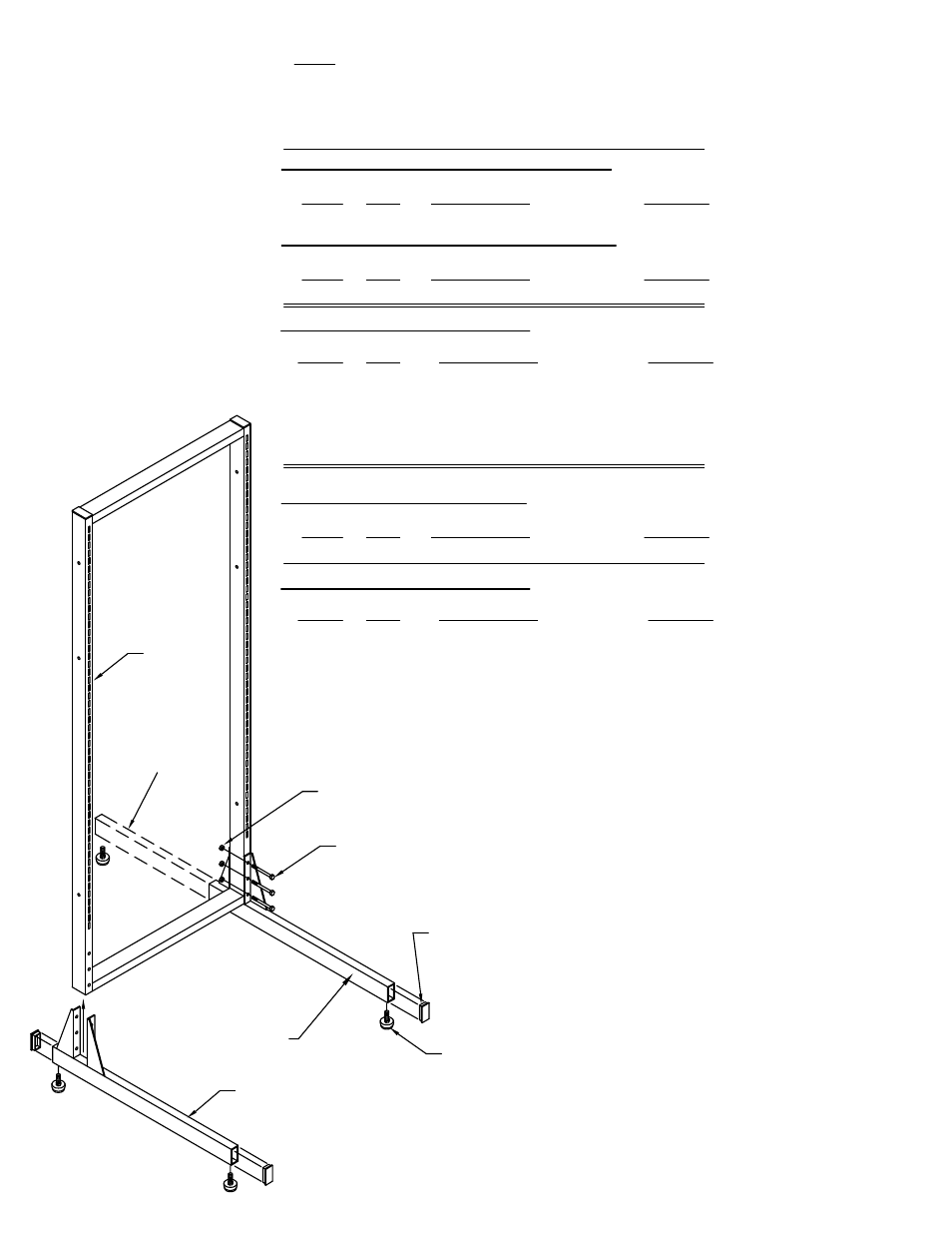
End Cap (E5)
Glide (E6)
DoubleLeg
Assembly (4)
Right Leg Assembly (3)
Left Leg Assembly (2)
5/16 -18
Hex Nuts (E7)
5/16 -18 x 2 3/4
Screws (E8)
** Denotes Color Code
~~Denotes Size
Frame (1)
2. Insert End Caps (E5) and
Glides (E6) into ends of Leg
Assemblies (2, 3 or 4).
3. Position Leg Assemblies under
the Frame and attach them with
5/16-18 x 2 3/4 Screws (E8) and
5/16-18 Hex Nuts (E7). Tighten all
nuts securely.
4. Level Frame by adjusting
Glides (E6).
When ordering components, specific color and/or size information may be required.
Contact a Mayline Customer Service Representative. 1-800-822-8037
NOTE: Please count and inspect all pieces before disposing
of any carton or packing materials.
LEG ASSEMBLY
(2)