Mayline Talon Tables v1 User Manual
Page 4
Adjustable Height Base Operation
Units with the adjustable height base adjust with the lever
located just to the inside of each leg frame. Gently pushing
the lever up to the top will release the mechanism and the
table should elevate. To lower, gently push up on the lever
with one hand and with the other hand simultaneously push
down on the desk top to the desired height. Excessive force is
not required to activate the levers and may result in damage
as well as trying to activate the lever in any other manner.
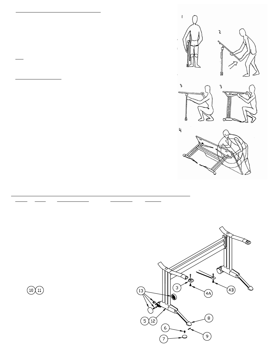
Folding Instruction
1. To begin the unfolding process the unit must first be in a
vertical position. See illustration #1 and #2
2. With the Talon table located in the vertical position, stand
on the side shown in illustration #2 and raise the top as
shown.
3. Holding the top in an elevated position, open one of the
legs until it reaches INITIAL POSITION. At this point you will
hear a "click" that will indicate the locating pin has secured
the top in the correct position. Repeat for opposite leg.
4. The Talon table must NEVER be assembled or
disassembled in the position shown in illustration #4.
Attempting to do so will result in severe damage to the table.
BASE WARRANTY PARTS IDENTIFICATION NOT INCLUDED IN ASSEMBLY
REF# QTY. DESCRIPTION PART NO. NOTES
3 2 Top Tube Cap. 2073054L *
4A 2 Locating Pin Assy. 8200230M * (Tube Design Frame)
4B 2 Locating Pin Assy. 8200230 * (Die Cast Arm Frame)
5 2 Shoe Assy. 8200235M * (2 Complete Shoes & Screws in one Bag)
6 2 Toe Cap Screw 8200213 *
7 2 Toe Cap Leveler 8200214M *
8 2 Toe Cap 8200215M *
9 2 Toe Cap Pin 8200212M *
10 2 Pneumatic Handle 8200248 * (Adjustable base only)
11 2 Handle Bracket 8200245 * (Adjustable base only
12 2/Shoe Screw For Shoe Assy. 8200232 *
13 1 Wheel Assy. 8200264 *
* Individual Items, Order by part number.
(4)
Not Shown.