Drive control & communication – Lenze TCF Series Drives Modbus Communications User Manual
Page 28
RG-TFMOD 24
Drive Control & Communication
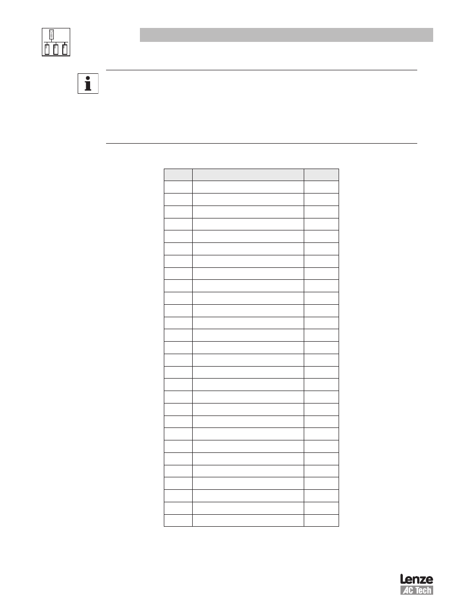
NOTE 4 - AC Tech Register #100, Parameter 50 - Fault History
When parameter #100 is read, the number of registers must be 4. The drive will send 8
bytes of data back to the MASTER. It does not mean read function reads parameter #100,
#101, #102, and #103. This is a special case to handle the data string. Number in every
byte represents fault in fault history. Latest fault is in the first data byte, oldest fault is in
the last data byte. Refer to table 17 for clarification.
Table 17: Fault Codes - Register 100
Code
Fault Description
Display
0
NO FAULT
1
TEMPORARY OUTPUT FAULT
2
OUTPUT (TRANSISTOR) FAULT
“OF”
3
HIGH DRIVE TEMPERATURE
“AF”
4
FLYING RESTART FAULT
“Rf”
5
HIGH DC BUS VOLTAGE
“HF”
6
LOW DC BUS VOLTAGE
“LF”
7
THERMAL OVERLOAD
“PF”
8
OEM FAULT
“GF”
9
ILLEGAL SETUP FAULT
“IL”
10
DYNAMIC BRAKE OVERHEATED
“dF”
11
SINGLE PHASE FAULT
“SF”
12
EXTERNAL
“EF”
13
CONTROL FAULT
“CF”
14
START ERROR
“UF”
15
INCOMPATIBILITY FAULT
“cF”
16
INTERNAL1 (EPM)
“F1”
17
INTERNAL2
“F2”
18
INTERNAL3
“F3”
19
INTERNAL4
“F4”
20
INTERNAL5
“F5”
21
INTERNAL6
“F6”
22
INTERNAL7
“F7”
23
INTERNAL8
“F8”
24
INTERNAL9
“F9”
25
PERSONALITY FAULT
“bF”
26
A/D OFFSET FAULT
“Ad”
27
SERIAL LINK FAULT
“JF”