4 product description, 1 function description, 2 area of application – Lenze MGXQK DC motors User Manual
Page 5: Product description
5
4. Product description
4.1 Function description
The motors of the MGXRK, MGXQU and
MGXQK series are separately excited DC
shunt motors.
The motors of the MGXRK series are
surface--cooled in IP54 enclosure and have a
round, ribbed housing. The motors of the
MGXQU and MGXQK series have a square
cross--section, are designed in IP23S
enclosure and internally ventilated.
The motors have fully--laminated stators and
are externally cooled by axially or radially
mounted blowers in their standard design
(type GF...). With reduced power, the motors
are also supplied with speed--dependent
self--ventilation (type GE...) and without
ventilation in self--cooled design (type GS...).
4.2 Area of application
n
Do not use in hazardous areas !
n
Fire risk !
Avoid contact with inflammable material !
¯
Ambient temperature must be up to
+40 5C, higher ambient temperature
require a power reduction.
¯
Installation height up to 1000 m above sea
level,
installation above 1000 m above sea level
requires a power reduction.
¯
Observe temperature class F (155 5C)
according to DIN--IEC 34 / VDE 0530. If the
limit temperature is exceeded, the
insulation is weakened and damaged.
¯
Enclosure to DIN--IEC 34 is IP54 or IP23S.
The actual enclosure can be obtained from
the nameplate (see chapter 4.4.)
¯
No tropical insulation.
¯
Designs (to DIN--IEC 34 part 7)
MGXRK:
IM B3, IM B5, IM B14
MGXQU, MGXQK: IM B35 and IM B34
The motors can be mounted in any
mounting position. Vertical arrangements
according to DIN--IEC 34 part 7 are
possible.
4.2.1 Other areas of application
¯
For other areas of application a power or
torque reduction is required using the
factors of the following table.
The permissible continuous power is
calculated from:
P’ = kJ ¡ k
h
¡
P
d
with P
d
being the permissible continuous
torque under normal conditions.
The torque can be calculated accordingly:
M’ = kJ ¡ k
h
¡
M
d
.
M
d
being the permissible continuous torque
under normal conditions.
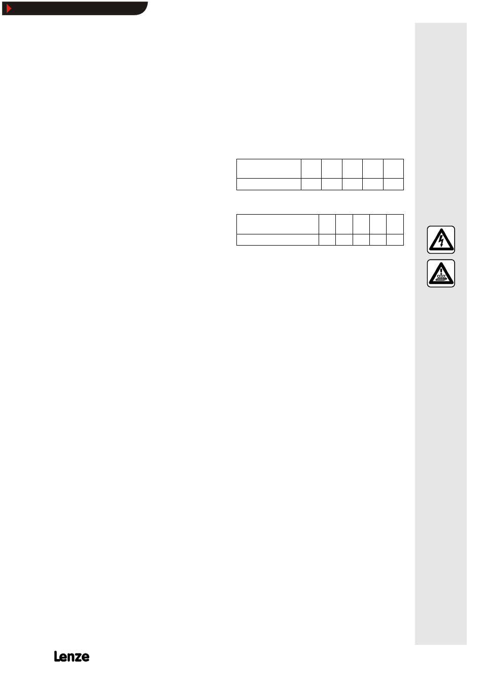
Cooling air temperature
5C
40
45
50
55
60
Power reduction
kJ
1.00
0.95
0.90
0.83
0.77
Power reduction with different ambient or cooling air
temperature
Installation height above sea
level in m
1000 2000 3000 4000 5000
Power reduction
k
h
1.00 0.92 0.83 0.77 0.67
Power reduction with different installation height
¯
If the actual form factor F
F
* ≥1.05, a power
reduction or torque reduction is also
required.
The permissible continuous load is calculated
from:
P’= ( 1.05 / F
F
* ) ¡ P
d
The torque is calculated as follows:
M’ = ( 1.05 / F
F
*) ¡ M
d
The form factor can be improved, among
others, by using armature chokes. Armature
chokes which are suitable for Lenze
controllers can be obtained from the technical
descriptions of the controllers or from your
nearest Lenze representative.
Show/Hide Bookmarks