5 parts for attachment – Lenze MGXQK DC motors User Manual
Page 11
11
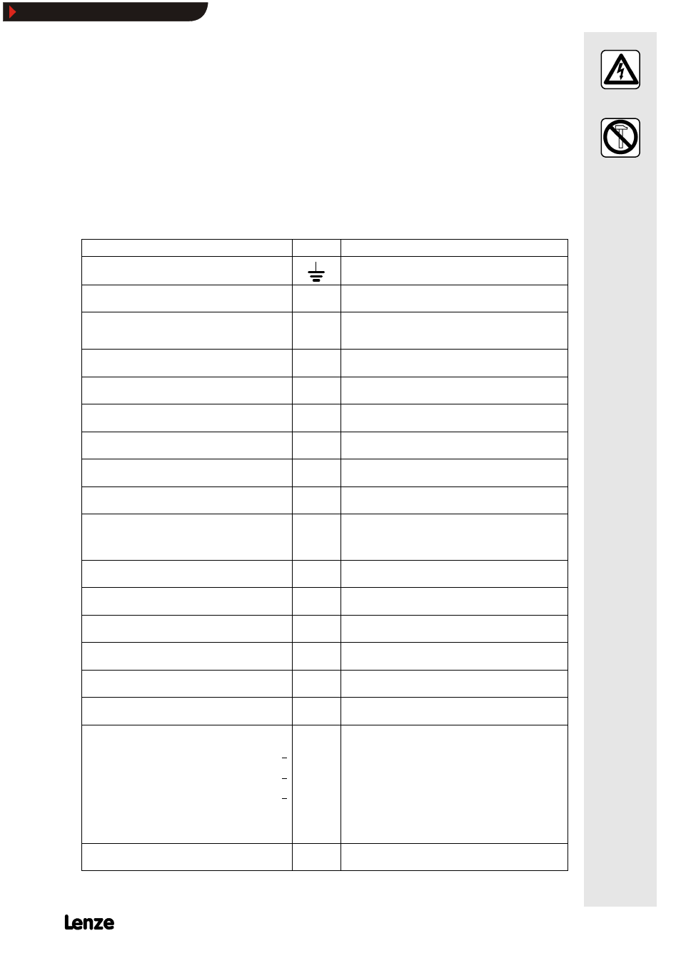
5.5 Parts for attachment
n
Attach parts to the drive only when no
voltage is applied!
n
Remove loads from the motor or secure
loads acting on the drive!
n
Do not use hammers or other impact tools
for assembly and dismantling!
¯
Motors with B--side attachments (brakes
and/or feedback sources) are assembled,
electrically connected and checked for
their function. Observe suitable operating
instructions.
¯
When brakes and/or feedback sources are
retrofitted, observe the following
connecting designations for additional
devices and attachments, the suitable
installation instructions and operating
instructions.
Connecting designations of additional devices and attachments to the terminal board or
terminal strips
Attachments
Terminal
Connection
Protective earth (SL)
Ground
External blower 1 µ
U1
U2
Connection to L1 - mains
Connection to N - mains
External blower 3 µ
U1
V1
W1
Connection to L1 - mains Observe direction of rotation!
Connection to L2 - mains Interchange
Connection to L3 - mains L1 - L2 in case of incorrect rotation
DC tacho
+
-
2A1
2A2
Polarity with CW rotation
AC tacho with rectifier
+
-
3A1
3A2
Polarity independent of the direction of rotation
Thermal contact (normally closed)
max. 250V µ
max. 1.6 A µ
S1
S2
Warning 1S1
switch-off 2S1
Warning 1S2
switch-off 2S2
Thermal contact (normally open)
max. 250V µ
max. 1.6 A µ
S3
S4
Warning 1S3
switch-off 2S3
Warning 1S4
switch-off 2S4
PTC
P1
P2
Warning 1P1
switch-off 2P1
Warning 1P2
switch-off 2P2
Brake DC excitation
+
-
Y1
Y2
Brake rectifier
1
4
2+
3-
Connection to L1 - mains
Connection to N - mains
Connection to brake Y1 (+ )
Connection to brake Y2 (-)
Brush indicator (normally closed)
Max. 28 V -
max. 4 A -
1H1
1H2
isolated
Brush indicator (normally open)
Max. 28 V -
max. 4 A -
1H3
1H4
isolated
Brush indicator (normally closed)
Max. 28 V -
max. 4 A -
2H3
2H4
not isolated 1st indication circuit
Brush indicator (normally open)
Max. 28 V -
max. 4 A -
3H3
3H4
not isolated 1st indication circuit
Standstill heating
E1
E2
24 V
Standstill heating
E3
E4
230V
Pulse encoder
Supply +
Supply -
Output channel A
Output channel A
Output channel B
Output channel B
Output channel C
Output channel C
Earth
Screen
Analog output
B1
B2
B3
B4
B5
B6
B7
B8
B9
B10
B11
Supply
GND (ground)
Inverse
Inverse
Zero track
Inverse
Resolver
-
Connection via system cable, connecting diagrams are attached to
the drive
Show/Hide Bookmarks