31 figure 13. adding to end of stack – Bay Technical Associates BayStack 400-ST1 User Manual
Page 33
31
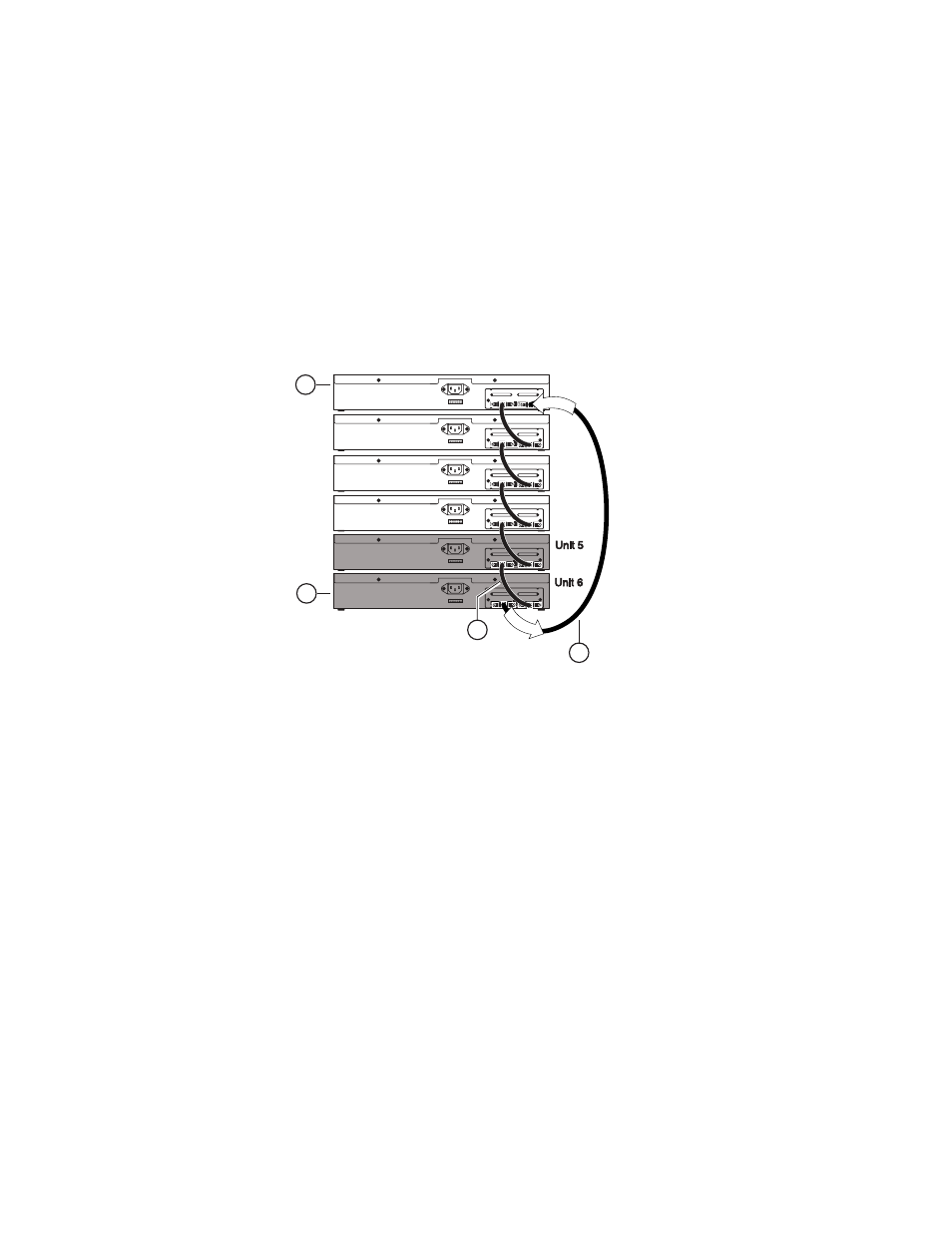
Figure 13.
Adding to End of Stack
2.
Disconnect the cascade max-return cable (item 4)
from the Cascade A Out connector at unit 4.
Leave the other end of the cascade max-return cable
connected to the Cascade A In connector at unit 1.
3.
Add the new units (units 5 and 6) to the end of the
stack configuration.
1 = Base unit
2 = Last unit
3 = Cascade cable (PN 303978-A)
4 = Cascade max- return cable (PN 303979-A)
BS0042A
Unit 2
Unit 1
Unit 4
Unit 3
2
1
Cascade Module
Cascade Module
Cascade Module
Cascade Module
Cascade Module
Cascade Module
4
In
O
ut
3