Drive control & communication – Lenze smd Series Drives User Manual
Page 20
RG-SDMOD 16
Drive Control & Communication
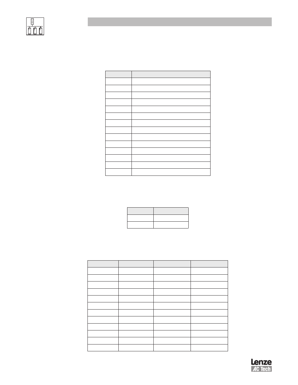
5.4.2 Operational Status - Register #26
Table 11 lists the Operational Status (Register #24 byte D3L or Register #26 DL)
Table 11: Operational Status
Bit
Parameter
0
FAULT LOCKOUT
1
FAULT
2
START PENDING
3
STOP
4
DC BRAKE
5
RUN AT 0Hz
6
RUN
7
ACCEL
8
DECEL
9
CURRENT LIMIT
10
DECEL OVERRIDE
11
LOWER TRANSISTORS SWITCHING ON
12
OFF
13
INHIBIT
5.4.3 Actual Rotational Direction - Registers #24 & 27
Table 12 lists the Actual Rotational Direction (Register #24 byte D4H or Register #27 DH).
Table 12: Actual Rotational Direction
Setting
Direction
0
FORWARD
1
REVERSE
5.4.4 Control Mode - Registers #24 & 27
Table 13 lists the Control Mode (Register #24 byte D4L or Register #27 DL).
Table 13: Control Mode
Control Mode Speed Source
Control Source
Program Source
0
Analog
Terminal
Keypad
1
c40
Terminal
Keypad
2
Analog
Terminal
LECOM
3
LECOM
LECOM
LECOM
4
Analog
Terminal
Remote Keypad
5
c40
Terminal
Remote Keypad
6
Analog
Remote Keypad
Remote Keypad
7
c40
Remote Keypad
Remote Keypad
8
Analog
Terminal
Modbus
9
c40
Terminal
Modbus
10
Analog
Modbus
Modbus
11
c40
Modbus
Modbus