Drive control & communication – Lenze smd Series Drives User Manual
Page 19
15 RG-SDMOD
Drive Control & Communication
5.4 Drive Status - Registers #24-29
5.4.1 Reading Register #24
When reading register #24, the group of words requested can be either 1 or 6. This is an exception to the
rule of being able to read only one register at a time. If 6 words are requested at register #24, the following
will be returned:
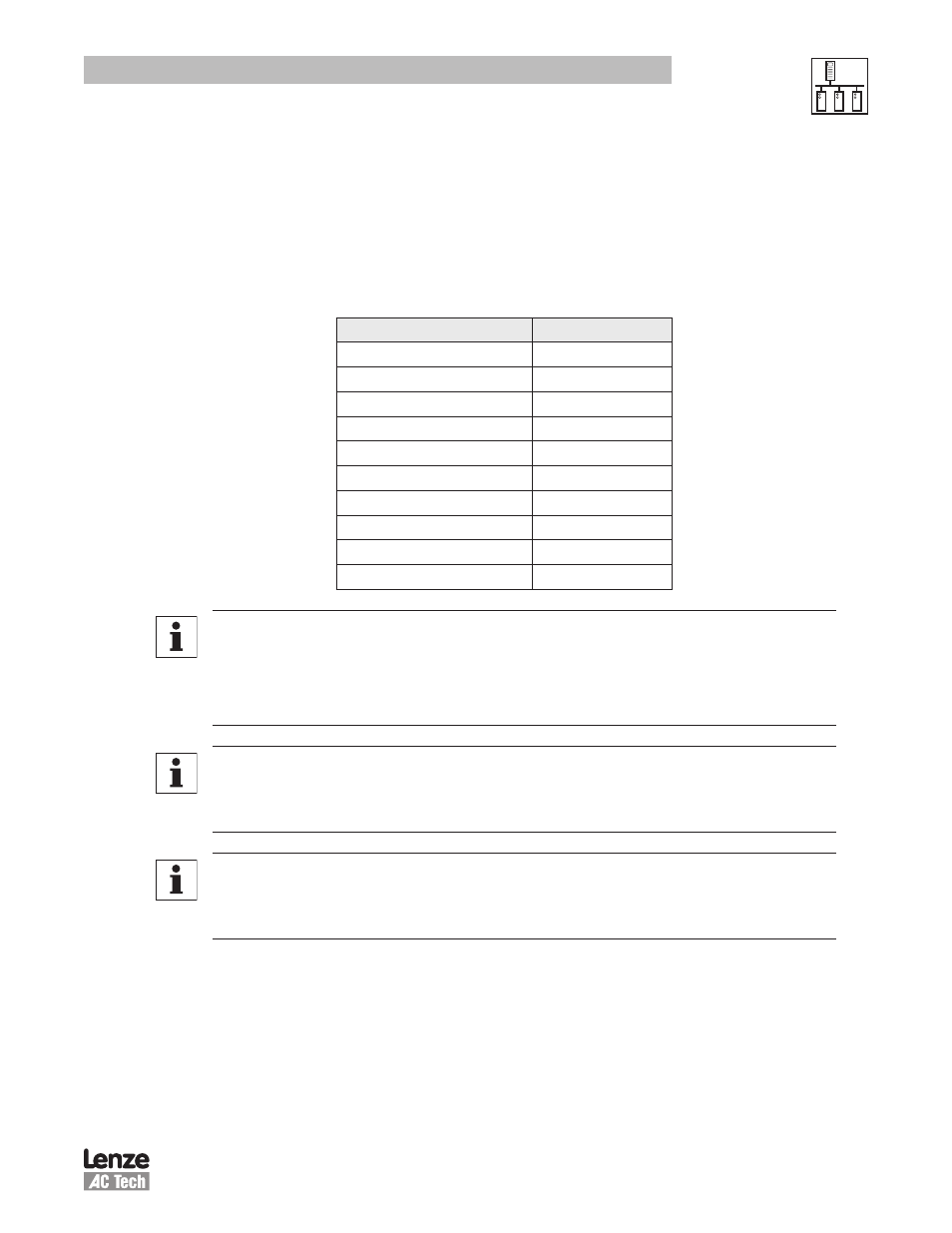
Table 10: 6 Register read at #24
Parameter
Data Byte
Command Speed
D1H D1L
Actual Speed
D2H D2L
Load
D3H
Operation Status
D3L
Rotational Direction
D4H
Control Mode
D4L
Speed Command Source
D5H
Speed Reference Status
D5L
Present Fault
D6H
Command Rotation
D6L
NOTE 4a - Command Speed (Register #24 Bytes D1H and D1L or Register #24)
• In tenths of a Hz
• Most significant byte is first, followed by Least significant
• Example: 02 01 in hex converts to 51.3Hz in decimal (assumed 1 decimal place).
NOTE 4b - Actual Speed (Register #24 Bytes D2H and D2L or Register #25)
• In tenths of a Hz
• Most significant byte is first, followed by Least significant
NOTE 4c - Load (Register #24 Byte D3H or Register #26 DH)
• In percent of full load
• Example: 64 (one byte in hex) ==> 100 in decimal ==> 100% (drive load).