Hydraulic diagram - vacuum fan motor system, Hydraulic diagram - vacuum fan motor system -28 – Kinze 3110 Mounted Planter Rev. 7/14 User Manual
Page 128
M0244-01
Model 3110
6-28
9/12
TM
Lubrication and Maintenance
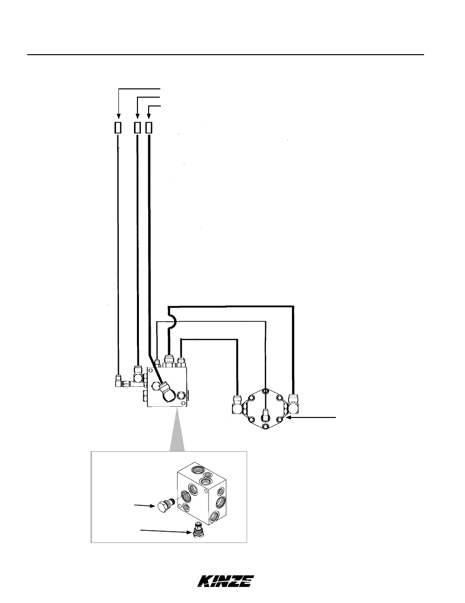
HYDRAULIC DIAGRAM - VACUUM FAN MOTOR SYSTEM
Fan Motor
Assembly
Case Drain (⅜" Hose)
Pressure (½" Hose)
Return (¾" Hose)
Vaccum Fan Motor Valve Block Assembly
(See Machine Operation Section)
Relief Valve
Check Valve
NOTICE
Connect hydraulic motor case drain to a case drain return line with
zero pressure on tractor or hydraulic motor will be damaged. DO
NOT connect hydraulic motor case drain to SCV outlet. Contact
tractor manufacturer for specific details on “zero pressure return”.