Connection diagram, Interfaces voltage supply – JUMO 705001 mTRON T - Central Processing Unit Data Sheet User Manual
Page 7
JUMO GmbH & Co. KG
Delivery address: Mackenrodtstraße 14
36039 Fulda, Germany
Postal address:
36035 Fulda, Germany
Phone:
+49 661 6003-0
Fax:
+49 661 6003-607
E-mail:
Internet:
www.jumo.net
JUMO Instrument Co. Ltd.
JUMO House
Temple Bank, Riverway
Harlow, Essex CM20 2DY, UK
Phone: +44 1279 635533
Fax:
+44 1279 635262
E-mail:
Internet: www.jumo.co.uk
JUMO Process Control, Inc.
6733 Myers Road
East Syracuse, NY 13057, USA
Phone: 315-437-5866
1-800-554-5866
Fax:
315-437-5860
E-mail:
Internet: www.jumousa.com
2014-08-22/00529105
Data Sheet 705001
Page 7/10
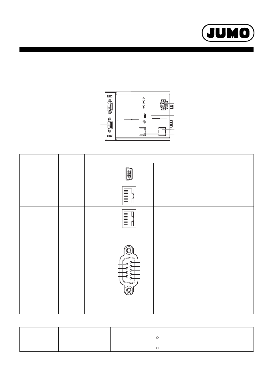
Connection diagram
The connection diagram included in the data sheet provides initial information about the connection options. Only use the installation instructions
or the operating manual for the electrical connection. The know-how and the correct technical implementation of the safety warnings/instructions
contained in these documents are the prerequisite for the installation, electrical connection, and initial start as well as for the safety during opera-
tion.
Interfaces
Voltage supply
Connection
Designation
Number
Connection element
USB device
Setup
(4)
System bus Out
Bus Out
(7)
1 TX+
2 TX-
3 RX+
6 RX-
Transmit data +
Transmit data -
Receive data +
Receive data -
Ethernet
LAN
(8)
1 TX+
2 TX-
3 RX+
6 RX-
Transmit data +
Transmit data -
Receive data +
Receive data -
Serial interface
(RS232), option
Com1,
Com2
(11),
(10)
2 RxD
3 TxD
5 GND
Receive data
Transmit data
Ground
Serial interface
(RS422), option
Com1,
Com2
(11),
(10)
3 TxD+
4 RxD+
5 GND
8 TxD-
9 RxD-
Transmit data +
Receive data +
Ground
Transmit data -
Receive data -
Serial interface
(RS485), option
Com1,
Com2
(11),
(10)
3 TxD+/RxD+
5 GND
8 TxD-/RxD-
Transmit/Receive data +
Ground
Transmit/Receive data -
PROFIBUS-DP,
option (as of system
version 02)
Com2
(10)
8 RxD/TxD-N (A)
3 RxD/TxD-P (B)
6 VP (+5 V)
5 DGND
Transmit/Receive data -
Transmit/Receive data +
Voltage supply +
Data ground
Connection
Designation
Number
Symbol and terminal designation
Voltage supply In
+24 V and GND
(2)
+24 V
GND
Setup
LAN
Bus Out
Run
Stop
Reset
Power
Status
Bus Error
Com1
Com2
Com2
2
1
3
4
ON
2
1
3
4
ON
Com1
(2)
(4)
(11)
(7)
(8)
(10)
8
1
8
1
6
7
8
9
2
3
4
5
1
U
+
-
x