Johnson Systems EDI-120 Control Retrofit User Manual
Page 8
8
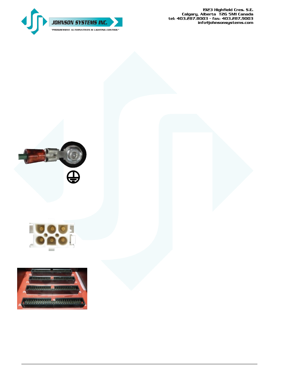
Ensure chassis is
connected to earth
ground.
POWER SUPPLY INPUT
120/208VAC, 3P4W, 1.3A, 60Hz
120/240VAC, 1P3W, 1.3A, 60Hz
EXTERNAL DISCONNECT REQUIRED
P1
If the connector needs to be moved, follow the following procedure:
First, remove the ten (10) #4-40 x 1/4” mounting screws that fasten the
lid onto the EDI-120 chassis. Remove the lid and set it aside, along
with the screws. Remove the metal cover plate on right-hand side P1
location by unscrewing the two (2) #4-40 x 1/4” mounting screws. Set
the cover plate aside, along with the screws. Release the P1 power
connector by carefully squeezing the tabs on each side of the connector
together and pushing the connector back. Cut and remove the wire-tie
securing the cable to the EDI-120 chassis via the bridge lance located
on the front-side of the chassis. The P1 connector/cable can now be
moved to the right-hand side location. Neatly route the cable and then
clip the P1 connector into place. Be sure the P1 connector is fully
seated and secure. Use a wire-tie to secure the cable to the chassis –
there is a bridge lance located above the power supply on the front-side
of the chassis. Reinstall the cover plate over the P1 connector opening
on the left-hand side of the chassis. Reinstall the lid.
• A 10’ (3m) yellow CAT 5e patch cable is supplied to daisy-chain the
DMX-A and DMX-B between multiple EDI-120 retrofit systems, in multi-
rack installations and racks containing more than 120 dimmer circuits. If
applicable, route the cable into place.
• Everything should now we prepared and ready for final installation of the
EDI-120 retrofit.
• Put the EDI-120 retrofit into a position where all the field wiring and
OEM wiring can be plugged in.
• Connect (plug in) in the green ground wire onto the EDI-120 chassis
connector.
• If applicable, connect (plug in) in the yellow CAT 5e patch cable.
• Connect (plug in) the prepared DMX input and thru connectors.
• Connect (plug in) the prepared input/output contacts connector.
• Connect (plug in) the prepared analog input connector.
• Connect (plug in) the prepared +12VDC power supply connector.
• Connect (plug in) the OEM P1 power connector.
• Connect (plug in) the OEM P3, P4, P5 and P6 ribbon cable connectors.
• All of the field wiring and OEM cables should now be connected
(plugged in).
• Be sure all connections are secure and fully seated.
• Slide the EDI-120 retrofit along the guide rails and into place. Be sure
not to pinch any of the cables.
On some earlier versions of EDI Mark VII dimmer racks, the guide rail
opening for the EDI-120 retrofit may be much narrower. If this is the
case, the guide rails will need to be removed. Once the guide rails are
removed, the EDI-120 retrofit will need to held in place and secured
using the mounting screws provided.
• Secure the EDI-120 retrofit using the four (4) #10-32 x 3/8” mounting
screws provided.