Control input, Status led indicators – Johnson Systems JS-ICON 624 ARCH Dimmer Rack User Manual
Page 9
www.johnsonsystems.com
8
www.johnsonsystems.com
9
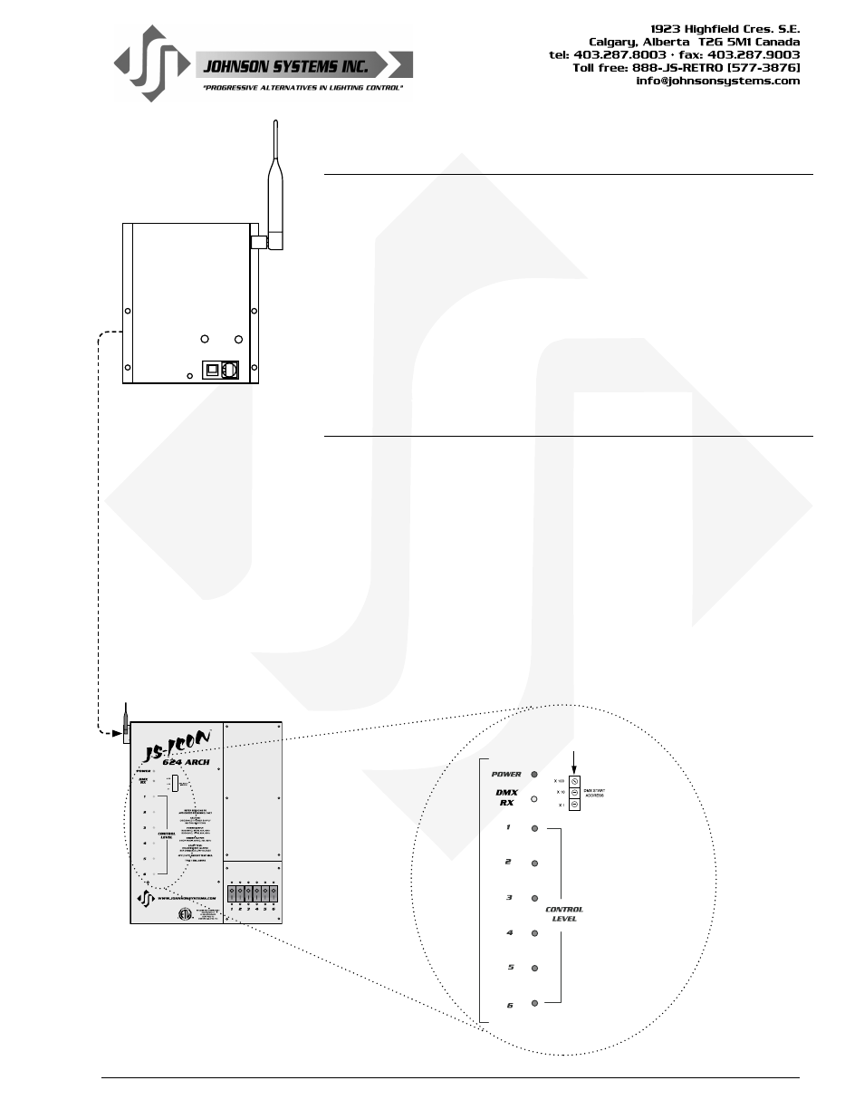
DMX START ADDRESS
SELECT SWITCHES
Status
LED
Indicators
POWER/DMX IN
RF OUT
RESET
ID
RADIO
CHANNEL
Control Input
The JS-ICON
™
624 ARCH accepts both DMX 512-A protocol and analog
0-10VDC. These control inputs are configured for HTP (highest takes
precedence) operation. DMX Data Input and DMX Data Thru is connected
via internal breakaway type connectors. Analog 0-10VDC is connected via
internal breakaway type connectors (see diagram on page 12).
Wireless DMX (WDS) is optional for all JS-ICON
™
Series dimming models.
The WDS (Wireless Dimming System) from City Theatrical has been selected
for its reliability and ease of use. The “WDS Kit” - supplied only by Johnson
Systems - can be easily adapted to all JS-ICON
™
products. It comes complete
with a wiring harness and mounting hardware, and installs quickly. For more
information, see the JS-ICON
™
Wireless DMX User Manual.
Status LED Indicators
POWER = Green
• ON when the on-board power supply is active, and the microcontroller is
running.
• FLASHES when there is a microcontroller failure.
• OFF when Phase-A power is off, or a power supply failure occurs.
RX = Amber
• ON when valid DMX signal is being received.
• FLASHES when invalid DMX signal is received.
• OFF when no DMX signal is present.
CONTROL LEVEL = Blue x 6 (1 per channel)
• ON when dimmer control is being received via DMX and/or analog.
• Intensity will increase with the level of control being received.
• OFF when no dimmer control levels are received via DMX and/or analog.
Wireless DMX Option