Power supply connection details, A b c – Johnson Systems JS-ICON 624 ARCH Dimmer Rack User Manual
Page 7
www.johnsonsystems.com
6
www.johnsonsystems.com
7
A B C
A B C
A B C
Three-Phase
Power Supply Input
Earth
Ground
Input
To Phase
Reference PCB
#18 AWG Wire
Factory Wiring To Breakers 1 - 6
#12 AWG Wire
Single-Phase
Power Supply Input
Earth
Ground
Input
To Phase
Reference PCB
#18 AWG
Wire
Factory Wiring To Breakers 1 - 6
#12 AWG Wire
Single-Phase
Power Supply Input
Earth
Ground
Input
To Phase
Reference PCB
#18 AWG
Wire
Factory Wiring To Breakers 1 - 6
#12 AWG Wire
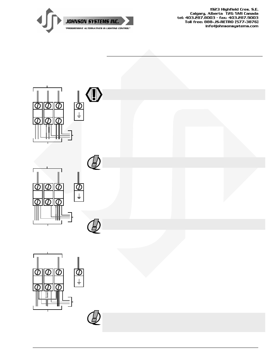
Power Supply Connection Details
The JS-ICON
™
624 ARCH is capable of various 120V power supply
configurations. Remove the contractor wiring access panel to locate the
contractor termination section, where the required power terminals are
located. Knockouts on the top and bottom of the chassis are provided for
wire/conduit entry to the power terminals.
WARNING: Wiring termination must be done by qualified personnel only!
Power Supply Configurations - Option 1:
Three-Phase with Internal Dimmer/Circuit Breaker Protection
120/208 VAC, 3Ø, 5-Wire up to 40 Amps per phase. Maximum 14.4kW total.
Use #2 to #12 AWG copper wire only, rated for 90°C minimum.
Torque power connections (A, B, C) to 5.0-5.6 NM (45-50 LB-IN).
Torque ground lug connection to 5.6 NM (50 LB-IN).
• Dimmers 1 and 2 are powered from Phase A.
• Dimmers 3 and 4 are powered from Phase B.
• Dimmers 5 and 6 are powered from Phase C.
NOTE: Power supply requires an external disconnect.
Power Supply Configurations - Option 2:
Single-Phase with Internal Dimmer/Circuit Breaker Protection
120/240 VAC, 1Ø, 4-Wire up to 60 Amps per phase. Maximum 14.4kW total.
Use #2 to #12 AWG copper wire only, rated for 90°C minimum.
Torque power connections (A, C) to 5.0-5.6 NM (45-50 LB-IN).
Torque ground lug connection to 5.6 NM (50 LB-IN).
• Dimmers 1, 2, and 3 are powered from Phase A.
• Dimmers 4, 5, and 6 are powered from Phase C.
NOTE: Power supply requires an external disconnect.
Three-Phase to Single-Phase Conversion
JS-ICON
™
systems are shipped from the factory ready for three-phase
operation unless otherwise specified at the time of purchase. The following
steps will need to be followed to convert the JS-ICON
™
from three-phase
operation to single-phase operation.
1. Remove wire #3 (red #12AWG wire, marked with black heat-shrink)
going from the B power terminal to breaker #3, and reconnect to A
power terminal (dimmers 1, 2, and 3 are now connected to Phase A).
2. Remove wire #4 (red #12AWG wire, marked with blue heat-shrink)
going from the B power terminal to breaker #4 and reconnect to C
power terminal (dimmers 4, 5, and 6 are now connected to Phase C).
3. Reconnect the red #18AWG phase reference wire to the B power
terminal.
NOTE: Be sure to set the 3-Phase/1-Phase select switch (located on the
Phase Reference Printed Circuit Board) to the correct position to ensure
proper dimming.