Bryant 355MAV User Manual
Page 17
A02350c
25
INV
ALID
MODEL
SELECTION OR
SETUP ERR
OR – If
status code 25 only
flashes 4 times on
po
wer-up the control is
missing its model plug PL4 and is
def
aul
ting
to the
m
odel selection store
d
in
memor
y.
If
status code 25 flashe
s
continuously
it
could indicate an
y of
th
e
follo
w
ing:
-
Model plug PL4 is
missing and
there is
no valid model
stored in per
manen
t
memor
y.
This w
ill happen if you f
orge
t
to install the model
plug PL4 on
a
ser
vice replacement
control
.
-
Ther
mosta
t call with SW1-1 ON.
-
Ther
mosta
t call with SW1-6 ON.
-
S
W
1-1 and SW1-6
both ON.
-
T
w
o
diff
eren
t
fur
na
ce models tw
inned.
31
HIGH-HEA
T PRES
SURE SWITCH OR
RELA
Y DI
D NO
T C
L
OSE
OR
REOPENED
- Check
fo
r:
-
Control rela
y
ma
y
be def
ectiv
e
.
-
Gas valv
e is mis
w
ired.
-
See status code
32
.
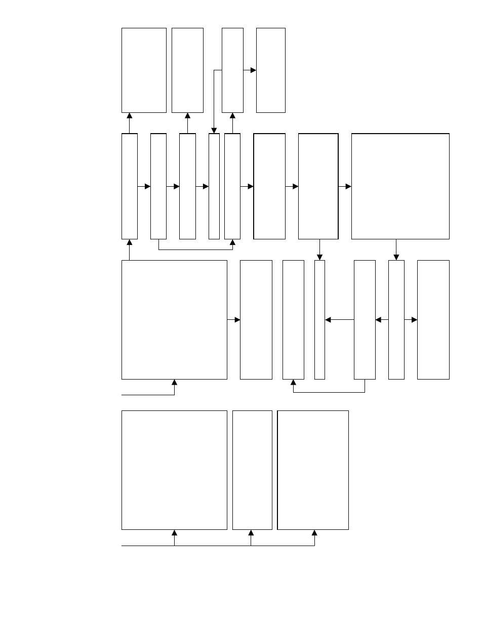
41
BLOWER M
O
T
O
R
F
A
U
LT
– Indicate
s
the
b
lo
w
er f
ailed
to reach 250 RPM or the
b
lo
w
er f
ailed
to
communicate within
the
prescr
ibed
time limits
.
Thir
ty
seconds
after
being tur
ne
d ON
or ten
seco
nds
dur
ing
steady-state operation
.
T
u
rn
po
off and chec
k the
fo
llo
wing items first
bef
ore
proceeding
to the ne
x
t
step
.
we
r
-
Rubbing b
lo
w
er
wheel.
-
Loose b
lo
w
er
wheel.
-
Wir
ing
from fur
na
ce
control to
blow
e
r
motor
.
Remo
v
e
the R
thermosta
t
connection
from
the fur
n
ace control,
disconnect both
connectors
from
the
b
lo
w
er motor PL1
3
and PL14
. Doe
s
th
e
b
lo
w
er wheel tur
n
freely
?
Replace the
b
lo
w
er control module attached to
the
b
lo
w
er motor.
F
ollo
w
the instructions with
the
b
lo
w
er control
module
to mak
e
sure the
entire
b
lo
w
er motor does not need to be
replaced.
T
u
rn
po
w
er bac
k o
n
.
Is there
115V
A
C
at
PL14-5 and PL14-4
?
NO
You ha
ve an open
w
ire or bad
ter
minal
on
either
the BLA
CK
or
WHITE
po
wer leads betw
een
the fur
n
ace control and the
b
lo
w
er motor
.
If you ha
v
e
a
po
wer chok
e di
sconnect it
and
check continuity
.
YES
NO
Is there
12-VDC at
PL13-7 RED
(+)
an
d
PL13-1 GREEN
(-)?
YES
NO
Is there
12-VDC at
PL3-1 RED
(+) and
PL3-2 GREEN
(-)
?
Replace the
fur
na
ce control.
NO
You ha
ve an open
w
ire or bad
ter
minal
on
eith
er
the RED or
GREEN wire between the
fur
na
ce
control and the
b
lo
w
er
motor
.
YES
YES
The voltage just measured
should
be
v
e
ry
stab
le and sho
uld
n
ot fluctu
ate
more
than .02-VDC
.
If the voltage
fluctuate
s
more than
this ge
t
a
diff
ere
nt voltmete
r
bef
ore
proceedin
g.
NO
T
u
rn
po
w
er off
, di
sconnect PL13 and
PL14
from
the
b
lo
w
er motor
, then
tur
n
po
wer bac
k on
.
Connect a DC voltmeter
across PL13-16
BLUE (+) and PL13-1
GREEN (-).
The v
o
ltage should
be near
0-VDC b
ut i
t will fluctuate brie
fly
se
v
e
ra
l
times a second
.
If
y
ou ha
v
e
an analog
v
o
ltmeter the needle will briefly
go high
se
v
e
ral times a
s
econd.
If you ha
v
e
a
digital voltmeter with a
bar
graph
it will
sho
w a large
change in magnitude on
the
bar gra
p
h
se
v
e
ral times a
second.
If you
ha
ve a standard di
gital voltmeter it will
sho
w a br
ie
f fluctuation
in voltage and the
magnitude ma
y
v
a
ry
depending on the
v
o
ltmeter used.
Does
the voltage
fluctuate as describe
d in
the
pre
v
ious step?
Replace the
b
lo
w
er control module attached to
the
b
lo
w
er motor.
F
ollo
w
the instructions with
the
b
lo
w
er control
module
to mak
e
sure the
entire
b
lo
w
er motor does not need to be
replaced.
NO
YES
Connect a
DC voltmeter a
c
ross
PL3-4
BLUE
(+) and PL3-2 GREEN (-)
.
Does
the voltage
fluctuate as describ
ed two
steps ba
c
k
?
You ha
v
e
an open
w
ire or bad
ter
mina
l on
the
BLUE wire between the
fur
na
ce
control and th
e
b
lo
w
er motor
.
NO
T
u
rn
po
w
er off
, re
connect
PL13
and
PL14 to the
b
lo
w
er motor
, then tur
n
po
wer bac
k on
.
Connect a DC voltmeter
across PL3-3
Y
E
LLOW (+)
and
PL3-2
GREEN (-).
Does
the voltage
fluctuate
more than it did
in
the pre
v
ious
step?
42
INDUCER MO
T
OR F
A
UL
T –
Indicates the
inducer motor has
not
started within 20
seconds after a
call
fo
r heat,
the inducer
motor RPM
is outside its valid range of
operation, or the inducer RPM
signal
w
a
s
lost f
or 5 se
cond
s
d
ur
ing
operation.
Check f
o
r:
-
Proper vent sizing
.
-
F
ailed indu
cer motor
.
-
Restr
icted comb
ustion
air supply
.
-
Improper motor wir
ing.
Replace the
fur
na
ce control.
Is there
5-VDC at
PL3-3
YELLOW
(+) and PL3-2
GREEN (-)?
You ha
ve an open
w
ire or bad
ter
minal
on
the
Y
E
LLOW wire
betw
een the
fur
na
ce control and
the b
lo
w
er
motor
.
NO
Is there 5-VDC at
PL13-16
Y
E
LLO
W
(+
)
and PL13
-1
GREE
N (-)?
YES
YES
NO
YES
YES
—17—