Bryant 355MAV User Manual
Page 11
The furnace control stores all status codes for a period of 72 hours,
regardless of 115-v or 24-v power interruption.
NOTE:
Removing blower access panel opens blower access
panel door switch and terminates 115-v power to furnace control.
Before removing blower access panel or turning off 115-v power,
look into blower access panel sight glass for current LED status.
1. To retrieve status code, proceed with the following:
NOTE:
NO thermostat signal may be present at furnace control
and all blower time delay periods must be completed.
a. Leave 115-v power to furnace turned on.
b. Remove main furnace door.
c. Look into blower access panel sight glass for current
LED status code.
d. Remove blower access panel.
e. Turn setup switch SW1-1 to ON position. (See Fig. 13 or
18 for location.)
f. Manually close blower access panel door switch. Use a
piece of tape to hold switch closed.
WARNING:
UNIT MAY NOT OPERATE
Failure to follow this warning could result in electrical
shock, personal injury, or death.
Blower access panel door switch opens 115-v power to
furnace control. No component operation can occur
unless switch is closed. Caution must be taken when
manually closing this switch for service purposes.
g. The AMBER LED will flash the status codes in the order
of occurence. Record status codes until status code 11
flashes (1 short and 1 long).
h. After status code # flashes, the status codes will repeat
until setup switch SW1-1 is turned off.
i. Remove tape to release blower access panel door switch
and replace blower access panel.
j. Operate furnace through 1 heat cycle to test for proper
operation and check LED status.
k. If furnace is operating properly and LEDs indicate
proper operation, replace main furnace door.
2. Status codes are erased after 72 hours or they can be
manually erased by performing the following procedure:
a. Leave 115-v power to furnace turned on.
b. Remove main furnace door.
c. Look into blower access panel sight glass for current
LED status code.
d. Remove blower access panel.
e. Turn setup switch SW1-1 to ON position. (See Fig. 13 or
18 for location.)
f. Jumper thermostat terminals R, W/W1, and Y/Y2 on
furnace control.
g. Manually close blower access panel door switch. Use a
piece of tape to hold switch closed.
h. After status code 11 flashes for at least 2 times, remove
R, W/W1, and Y/Y2 jumpers.
i. Turn setup switch SW1-1 to OFF position.
j. Remove tape to release blower access panel door switch
and replace blower access panel.
k. Operate furnace through 1 heat cycle to check for proper
operation and check LED status.
l. If furnace is operating properly and LEDs indicate proper
operation, replace main furnace door.
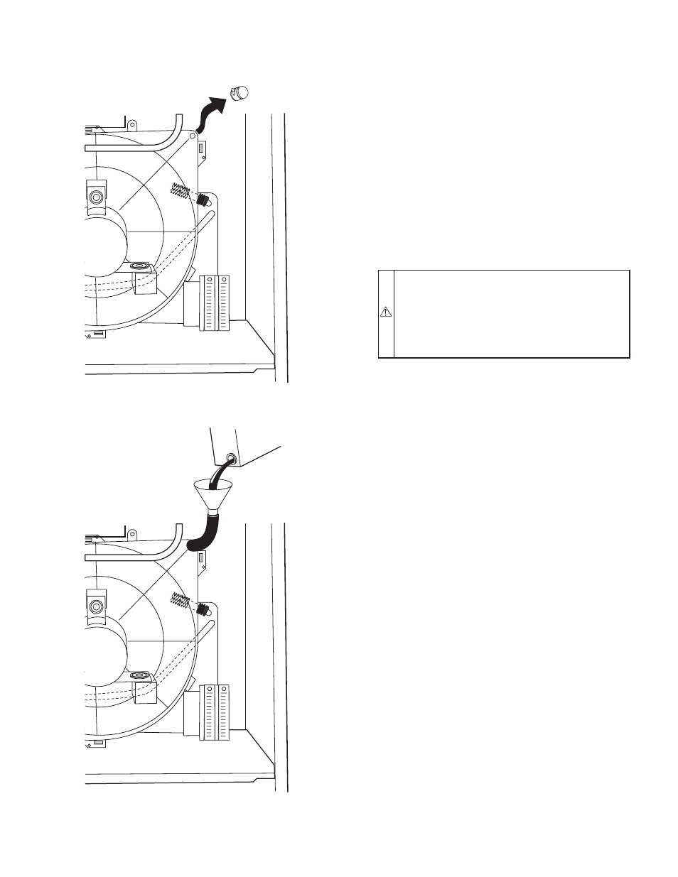
Fig. 15—Inducer Housing Drain Tube
A99118
Fig. 16—Funnel in Drain and Antifreeze Running
Through Trap
A99119
—11—