2 hardware concept, 1 hardware block diagram, Research & development – INFICON Spot CDS550D User Manual
Page 3
Research & Development
SPOT CDS500D & CDS550D OEM Sensor SPI-Interface Specification_V1.1
Page 3 of 14
Christian Berg, T based on Felix Mullis, TL
Created 11/10/2014 2:36:00 PM
2 Hardware Concept
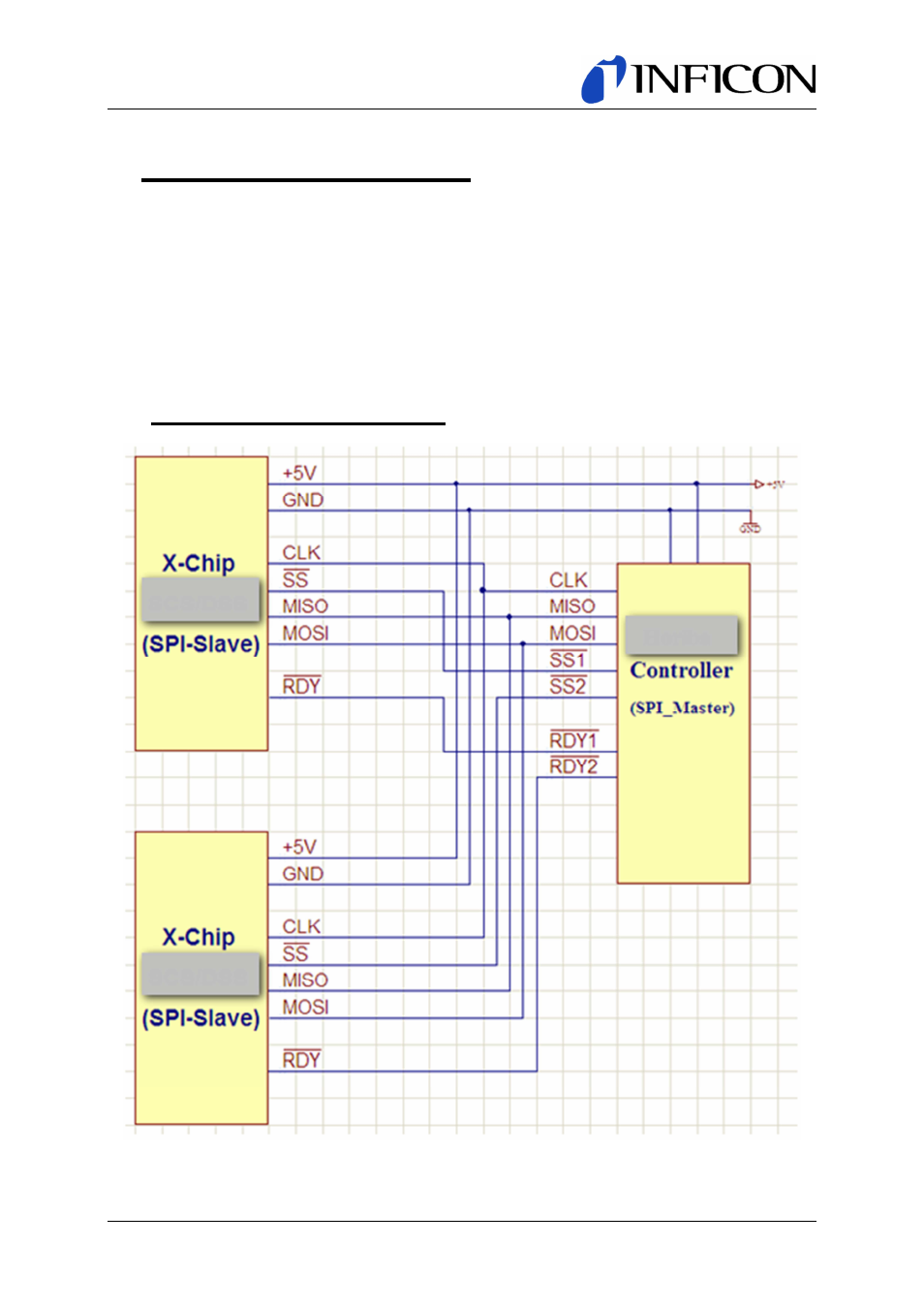
This section describes how two or more SPOT CDS5xxD slaves must be physically connected togeth-
er with a master. When doing so, the master will be able to receive pressure and temperature data
from each SPOT CDS5xxD slave.
The data exchange link consists of a simple SPI-Interface; therefore only three lines and a chip select
signal are necessary. The additional RDY/ lines signal the end of a measurement cycle. It must be
used in noise critical applications. There it’s forbidden to read data from the chip during measurement
cycles. (Crosstalk from the SPI-interface to the measurement data)
2.1 Hardware Block Diagram
Figure 2.1-1: SPI Block Diagram