Switching amplifier mode of operation, 3 switching amplifier mode of operation – INFICON VSC150A absolute switch, passiv User Manual
Page 7
1.3.3 Switching Amplifier Mode of Operation
A switching amplifier is required for each Vacuum
Switch. The output relay supplied with heavy-duty chan-
ge-over contact is energized when the pressure drops
below the value preset on the Vacuum Switch, i.e. if the
contact between diaphragm and contact pin in the refe-
rence chamber opens by flexing of the diaphragm. The
built-in slide switch (Fig. 5) must be set to the connected
type of Vacuum Switch.
7
7
tina42e1 (2005-03) VSC150.ga
tina42e1 (2005-03) VSC150.ga
1.3.3 Switching Amplifier Mode of Operation
A switching amplifier is required for each Vacuum
Switch. The output relay supplied with heavy-duty chan-
ge-over contact is energized when the pressure drops
below the value preset on the Vacuum Switch, i.e. if the
contact between diaphragm and contact pin in the refe-
rence chamber opens by flexing of the diaphragm. The
built-in slide switch (Fig. 5) must be set to the connected
type of Vacuum Switch.
9
(R)
(M)
10
9
(R)
(M)
8
7
6
5
4
3
2
1
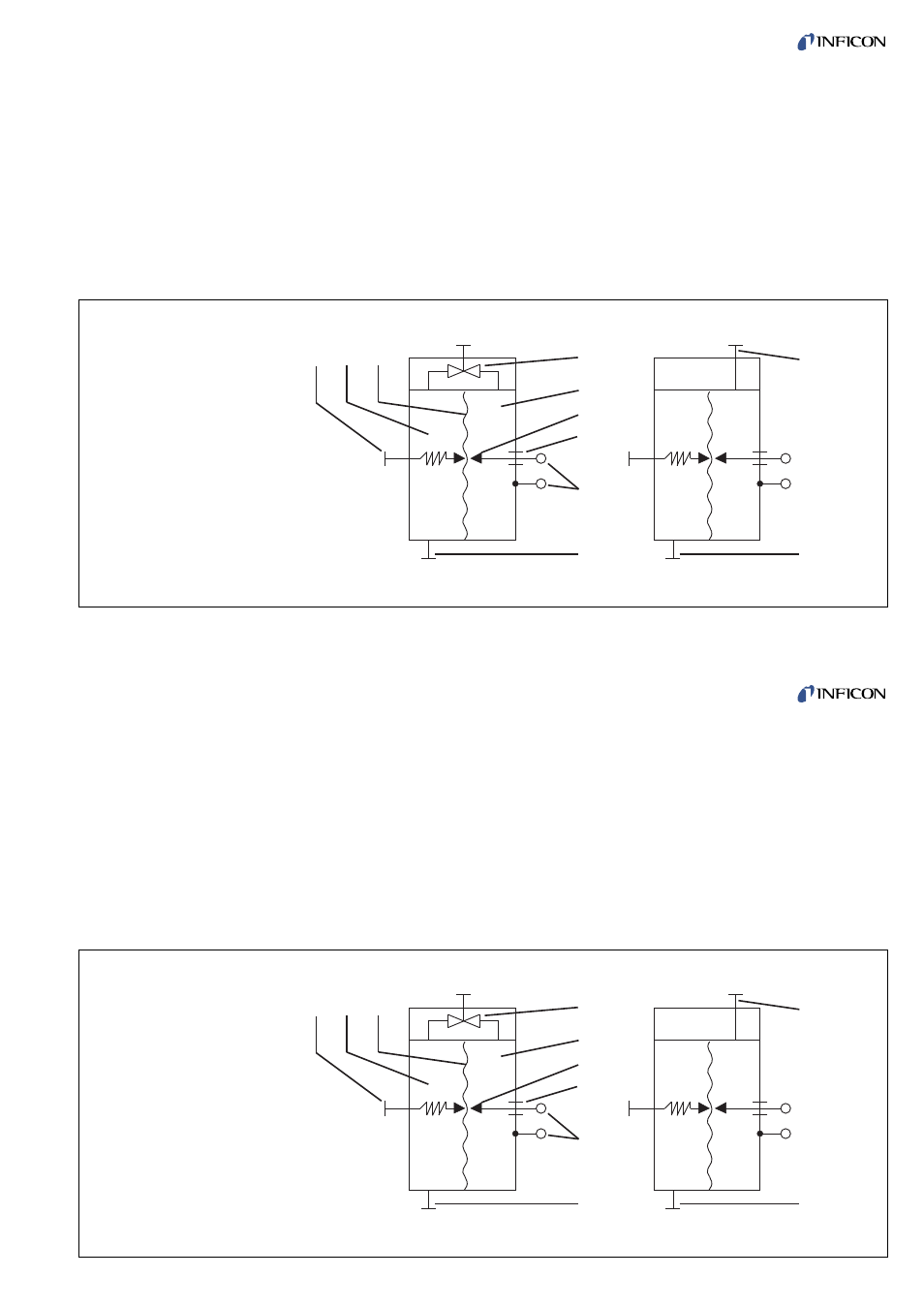
Fig 1 Schematic diagram of the Vacuum Switches
Key to Fig. 1
1
Adjusting Screw
2
Sensing chamber (M)
3
Diaphragm
4
Adjusting valve
5
Reference volume (R)
6
Contact pin
7
Current leadthrough
8
Electrical connection
9
Vacuum connection flange
10 Differential pressure adapter
9
(R)
(M)
10
9
(R)
(M)
8
7
6
5
4
3
2
1
Fig 1 Schematic diagram of the Vacuum Switches
Key to Fig. 1
1
Adjusting Screw
2
Sensing chamber (M)
3
Diaphragm
4
Adjusting valve
5
Reference volume (R)
6
Contact pin
7
Current leadthrough
8
Electrical connection
9
Vacuum connection flange
10 Differential pressure adapter