Sv switching amplifier, 2 sv switching amplifier – INFICON VSC150A absolute switch, passiv User Manual
Page 12
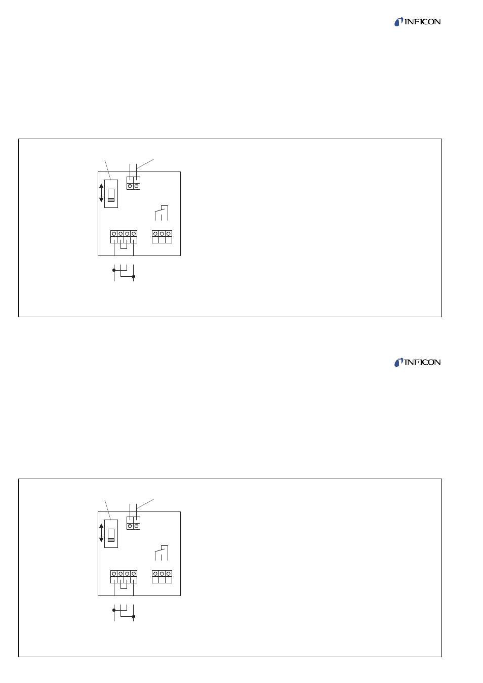
2.2.2 SV Switching Amplifier
The diaphragm contact in the Vacuum Switch is unilate-
rally connected to ground and designed for a maxi-
mum load of 24 V / 10 mA.
The built-in slide switch (5/1) must be set to the connec-
ted type of pressure switch. For electrical installation the
switching amplifier SV 110 is delivered set for
220 ... 240 VAC. For mains voltages of 110 ... 130 VAC
change terminal bridge connectors as shown in Fig. 5.
When connecting to the mains the VDE 0100 re-
gulations must be observed. The connection of the
external consumer which is to be switched is shown in
Fig. 5.
12
12
tina42e1 (2005-03) VSC150.ga
tina42e1 (2005-03) VSC150.ga
2.2.2 SV Switching Amplifier
The diaphragm contact in the Vacuum Switch is unilate-
rally connected to ground and designed for a maxi-
mum load of 24 V / 10 mA.
The built-in slide switch (5/1) must be set to the connec-
ted type of pressure switch. For electrical installation the
switching amplifier SV 110 is delivered set for
220 ... 240 VAC. For mains voltages of 110 ... 130 VAC
change terminal bridge connectors as shown in Fig. 5.
When connecting to the mains the VDE 0100 re-
gulations must be observed. The connection of the
external consumer which is to be switched is shown in
Fig. 5.
2
1
VSC150
220....240 VAC
110....130 VAC
A B
1 2 3 4
121113
Key to fig. 5
1 Slide switch for selecting the type of
connected pressure switch
2 Signal connection (from the Vacuum Switch)
Cable cross section
max. 1.5 mm
2
Cable connection
PG 9
Cable diameter
(outside dia.)
4.5 to 7 mm
Fig. 5 Connection diagram of the SV switching amplifier
2
1
VSC150
220....240 VAC
110....130 VAC
A B
1 2 3 4
121113
Key to fig. 5
1 Slide switch for selecting the type of
connected pressure switch
2 Signal connection (from the Vacuum Switch)
Cable cross section
max. 1.5 mm
2
Cable connection
PG 9
Cable diameter
(outside dia.)
4.5 to 7 mm
Fig. 5 Connection diagram of the SV switching amplifier