HYDAC HDA 5500-3-2-DC-000 User Manual
Page 6
HDA 5500 User Manual
- 6 -
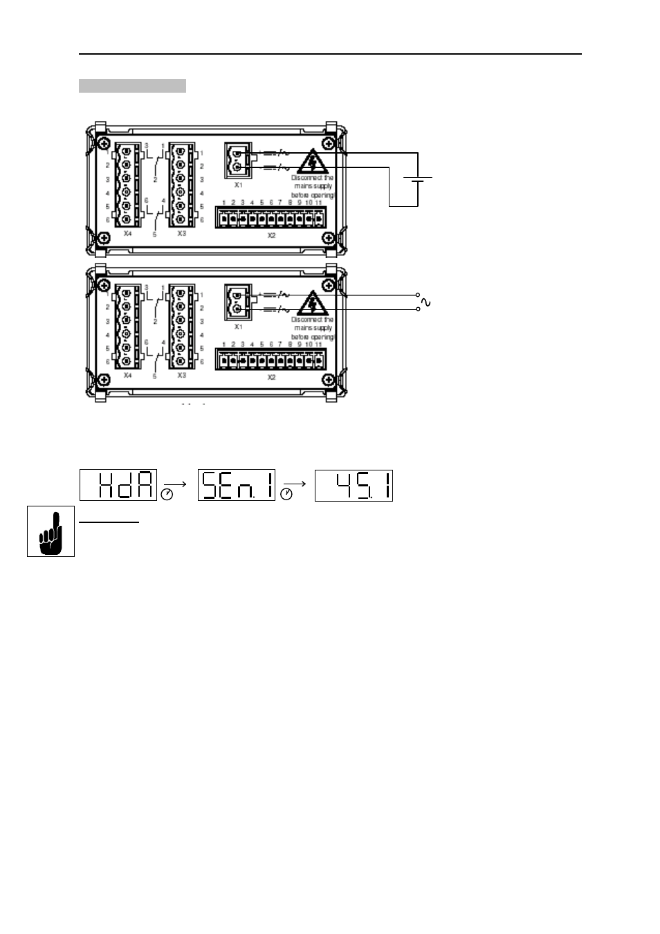
6.3 Supply voltage
The supply voltage is connected to terminal X1.
After switching on the supply voltage, the unit displays HdA for approximately 2 s. Then the
number of the sensor set as the primary display is shown. After a further approximately 2 s
the actual value is displayed.
Important:
Before sensors are connected, the HDA 5500 must be set appropriately.
If there is no input signal, then the following will be displayed, depending on the type of
signal:
•
Starting value of the measuring range - flashing (for sensors with 4..20 mA)
•
Starting value of the measuring range (for sensors with 0..10 V)
•
Final value of the measuring range - flashing (for Pt 100 sensor)
12..32 VDC
HDA 5500–3–X–DC–000
(see type code label)
85..265 VAC 50 / 60 Hz
HDA 5500–3–X–AC–000
(see type code label)
2 s
2 s