HYDAC HDA 5500-3-2-DC-000 User Manual
Page 11
HDA 5500 User Manual
- 11 -
Menu point
Setting
Setting range
Default setting
Allocation of analogue output to sensor (ouT.S)
Analogue output allocated to sensor 1
Analogue output allocated to Pt100 sensor
SEn.1
SEn.2
SEn.1
Output signal (ouT.M)
4..20 mA output signal
0..10 V output signal
MA
VoLT
VoLT
Software version (VErS)
Display of the software version (for reference only)
To close basic settings (End)
Basis settings menu closes.
Changed settings are saved.
Basic settings can still be altered.
YES
no
no
8 Connecting sensors
One analogue input for a transmitter or sensor is always available as standard. The particular
types of HDA 5500 described here have a further Pt 100 input.
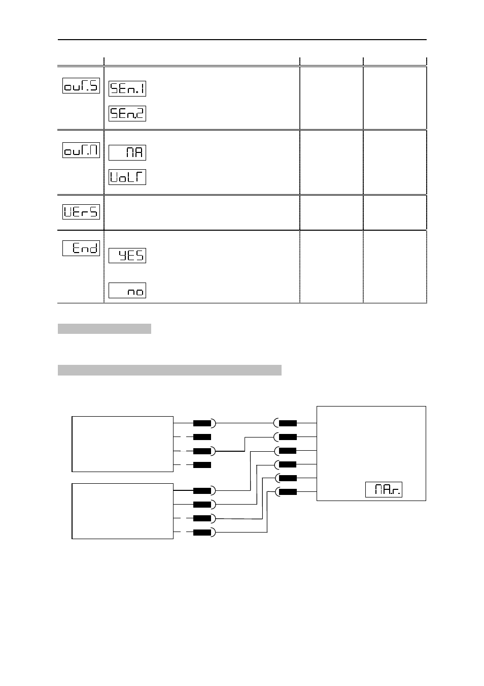
8.1 HDA 5500 with one transmitter and Pt 100 sensor
Connection example for one transmitters (sensors) with a 4..20 mA sink as input signal and
one Pt 100 sensor, e. g. HDA 5500-3-2-DC-000 with HDA 4746-A-100-000 and TFP 100
(refer to chapter 16 Pin connections):
HDA 4746-A-...
1
2
3
4
HDA 5500-...
Input signal
sensor 1:
6
7
8
9
TFP 100
1
2
3
4
IN1
+12V
10
11
Pt 100
Pt 100
Pt 100
Pt 100