HYDAC HDA 5500-3-2-DC-000 User Manual
Page 13
HDA 5500 User Manual
- 13 -
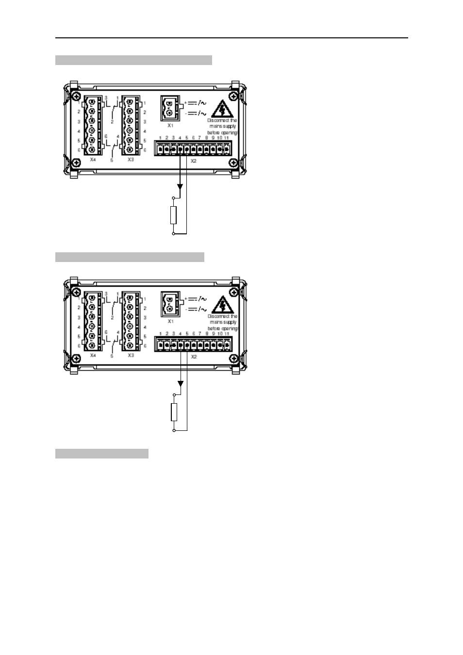
10.1.1 Analogue output set to 4..20 mA
Connection example for analogue output set to 4..20 mA:
10.1.2 Analogue output set to 0..10 V
Connection example for analogue output set to 0..10 V:
10.2 Switching outputs
Each switching output consists of a relay, the switching contacts of which can be connected
as N/C or N/O. For each switching output, the following parameters can be set during normal
operation (see chapter 7.2 Summary of the Basic Settings Menu):
•
Assignment to sensor
•
Switching function (switch point and hysteresis or switching window mode)
•
Switching direction (relay activated or relay deactivated)
•
Switch-on delay
•
Switch-off delay
Analog. Out
AGND
RL
min
2,000
V
out
= 0..10 V
AGND
RL
max
= 400
I
out
= 4..20 mA
Analog. Out
This manual is related to the following products: